Lifting locating pin

A technology of lifting positioning and positioning seat, applied in the field of positioning device and mechanical parts processing, can solve the problems such as the process hole and the positioning pin cannot be overlapped, the positioning pin is easy to break, the clamping and positioning are difficult, etc., and the structure is simple and not easy to bump. , the effect of low cost

Active Publication Date: 2015-04-08
XINXING HEAVY IND HUBEI 3611 MECHANICAL
View PDF5 Cites 3 Cited by
  • Summary
  • Abstract
  • Description
  • Claims
  • Application Information

AI Technical Summary

Problems solved by technology

Since the positioning pins are below the positioning plane of the workpiece, and some large and heavy parts such as flywheel housings, cylinder blocks, and cylinder heads have limited physical strength when clamping and moving, the process holes and positioning pins of the workpiece are often unable to be observed because the positioning pins cannot be observed. Overlapping, clamping and positioning are very difficult. Sometimes the workpiece directly collides with the positioning pin because it moves back and forth and cannot be moved. In this way, the workpiece is bumped and the positioning pin is easy to break

Method used


Image

  • Lifting locating pin
  • Lifting locating pin
  • Lifting locating pin

Examples


Embodiment Construction

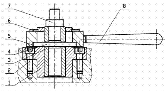
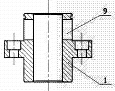
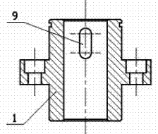
[0013] figure 1 Among them, the positioning seat 1 is fixed on the bottom plate by the screw 2, the lifting pin cover 3 is installed in the inner hole of the positioning seat 1, the bayonet pin 4 is inserted into the vertical guide groove 9 of the positioning seat 1 and the side hole of the lifting pin cover 3, and the rotation The ring 5 is set on the positioning seat 1, the bayonet pin 4 is inserted into the spiral guide groove 10 of the rotating ring 5, and there is a clamp spring 6 for the shaft preventing the rotating ring 5 from falling off from the positioning seat 1 above the rotating ring 5, and the handle 8 passes through the screw thread. Fixed on the rotating ring 5, the positioning pin 7 is interference fit in the lifting pin sleeve 3 holes.

[0014] Rotate the handle 8 on the rotating ring 5, and the helical guide groove 10 in the rotating ring 5 promotes the bayonet pin 4 to move up and down, and the bayonet pin 4 drives the lifting pin sleeve 3 to move up and d...


PUM


Abstract

A lifting locating pin comprises a locating seat which is fixed to a bottom plate, wherein the locating seat comprises a barrel; a flange which outwards protrudes and is used for being fixed with the bottom plate is arranged on the outer wall of the barrel; a lifting pin sleeve is mounted in the barrel of the locating seat; a locating pin is inserted into the upper end of the lifting pin sleeve; two vertical guide slots which are symmetrical with respect to the central axis of the barrel are formed in the barrel and above the flange of the locating seat; two assembly holes are formed in positions, corresponding to the lower parts of the vertical guide slots, of the lifting pin sleeve; a rotating ring sleeves the outside of the barrel part above the flange of the locating seat; two spiral guide slots are correspondingly formed in the inner wall of the rotating ring; a bayonet lock is inserted into the vertical guide slots and the two assembly holes of the lifting pin sleeve; two ends of the bayonet lock are arranged in the spiral guide slots in the inner wall of the rotating ring. According to the invention, a workpiece clamping problem on a workpiece processing line is solved, time is saved, the work efficiency is improved, the product quality is ensured, bump is effectively prevented, and the lifting locating pin is particularly suitable for one-face two-pin location of a heavy product with a relatively large size.

Description

technical field [0001] The invention belongs to a positioning device in the processing industry of mechanical parts, in particular to a liftable positioning pin. Background technique [0002] At present, in the machining industry, the processing technology of parts is generally positioned with two pins on one side. The two positioning pins used in the traditional processing technology are all fixed. When the processed parts are clamped, the two process holes on the workpiece can be coincident with the positioning pins by observing with eyes. Since the positioning pins are below the positioning plane of the workpiece, and some large and heavy parts such as flywheel housings, cylinder blocks, and cylinder heads have limited physical strength when clamping and moving, the process holes and positioning pins of the workpiece are often unable to be observed because the positioning pins cannot be observed. Overlapping, clamping and positioning are very difficult. Sometimes the wor...

Claims


Application Information

Patent Timeline
Patent Type & Authority Applications(China)
IPC IPC(8): F16B19/02B23Q3/06
CPCB23Q3/06F16B19/02
Inventor 颜志军万龙飞王锋樊小敏
Owner XINXING HEAVY IND HUBEI 3611 MECHANICAL
Why Eureka
Try Eureka