Infrared energy gathering combustor

An infrared and burner technology, used in burners, burners, gas fuel burners, etc., can solve problems such as high maintenance costs, explosive porcelain, and inability to remove from the burner, saving maintenance costs and ensuring use. safe effect

Inactive Publication Date: 2015-04-08
CHINABEST HOME APPLIANCE
View PDF4 Cites 0 Cited by
  • Summary
  • Abstract
  • Description
  • Claims
  • Application Information

AI Technical Summary

Problems solved by technology

[0002] As we all know, there are two main types of burner heads for gas stoves on the market, one is the enamel burner head, and the other is the combination burner head (the burner head that combines different materials together). Under high-temperature baking, it is easy to explode the porcelain and cause the furnace head to perforate, resulting in air leakage; while the combination furnace head will be easily deformed under long-term high-temperature baking, and then air leakage will occur. Therefore, whether it is an enamel furnace head or a combination furnace head, there are potential safety hazards of air leakage
[0003] In addition, there are some infrared burners on the market. This kind of infrared burner mainly adds an infrared generator on the burner, and heats the infrared generator by burning gas. When the infrared generator reaches a certain temperature, it will generate Infrared, although this kind of infrared burner can improve the heating efficiency of heat, but the infrared generator is easy to be damaged under long-term high-temperature baking, and most of the infrared burners on the market now adopt the method of snapping the infrared generator to the The structure on the burner, when the infrared generator is baked at high temperature for a long time, the infrared generator is easily bonded to the burner and cannot be removed from the burner. When the infrared generator is damaged, people can only replace it The whole burner can not replace the infrared generator separately, and the maintenance cost is high

Method used


Image

  • Infrared energy gathering combustor
  • Infrared energy gathering combustor
  • Infrared energy gathering combustor

Examples


Embodiment Construction

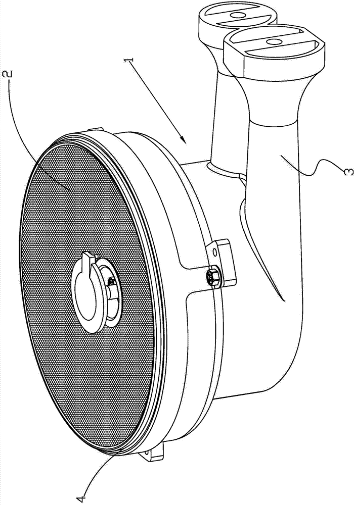
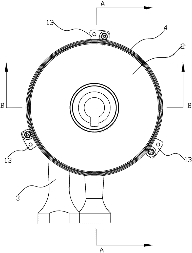
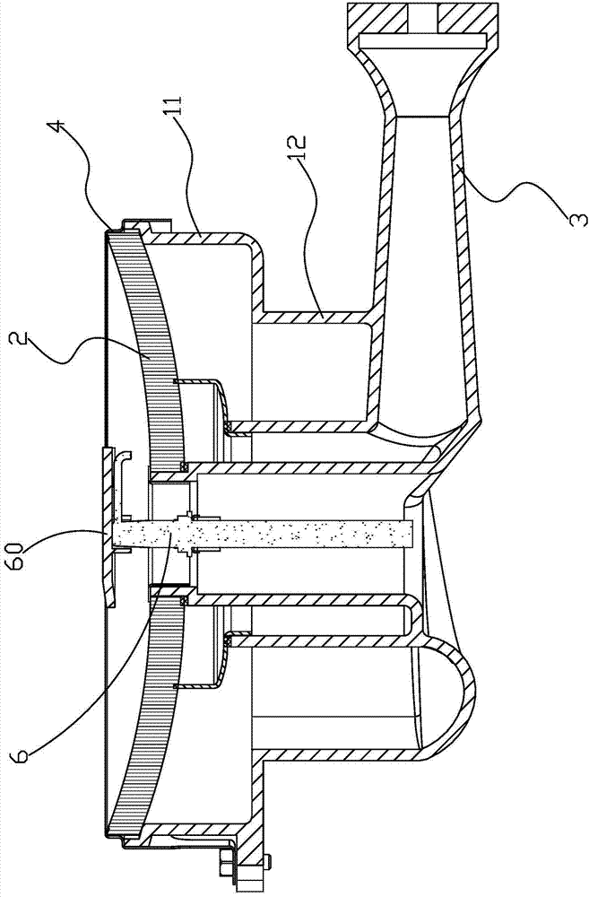
[0027] refer to figure 1 As shown in Fig. 9, the infrared concentrated energy burner includes a burner main body 1 which is hollow inside. The burner main body 1 is integrally cast and formed and the shape of the burner main body 1 is in the shape of a round platform with a large upper part and a smaller lower part. The burner main body 1. At the opening of the end face of the large-diameter section 11 on the upper part, there is an infrared generator 2 that can generate infrared rays after being heated. On the side wall of the small-diameter section 12 on the lower part of the burner main body 1, an ejector tube for conveying gas is connected. 3. The injection tube 3 communicates with the interior of the burner body 1 . Since the burner main body 1 of the present invention adopts an integrally cast structure, the burner main body 1 will not be deformed or cracked even if it is baked at a high temperature for a long time, which effectively prevents leakage caused by the crack ...


PUM


Abstract

The invention discloses an infrared energy gathering combustor which comprises a furnace end main body with a hollow inner part, wherein the furnace end main body is integrally cast and formed, and takes the shape of a circular truncated cone with a larger upper part and a smaller lower part; an infrared ray generation piece which is heated to generate infrared rays is arranged at an opening in the end face of the large-diameter section of the upper part of the furnace end main body; the side wall of the small-diameter section at the lower part of the furnace end main body is connected with an ejection pipe for conveying fuel gas in an extending manner; the ejection pipe is communicated with the inner part of the furnace end main body. The furnace end main body of the infrared energy gathering combustor is of an integrally cast structure, so that deformation or cracking of the furnace end main body can be avoided under the condition of long-time high-temperature baking; the phenomenon of gas leakage caused by the cracking or the deformation of the furnace end main body is effectively prevented, and the use safety is guaranteed.

Description

technical field [0001] The invention relates to a burning appliance, in particular to an infrared concentrated energy burner capable of generating infrared rays. Background technique [0002] As we all know, there are two main types of burner heads for gas stoves on the market, one is the enamel burner head, and the other is the combination burner head (the burner head that combines different materials together). Under high-temperature baking, it is easy to explode the porcelain and cause the furnace head to perforate, resulting in air leakage; while the combination furnace head will be easily deformed under long-term high-temperature baking, and then air leakage will occur. Therefore, whether it is an enamel furnace head or a combination furnace There is a safety hazard of air leakage. [0003] In addition, there are some infrared burners on the market. This kind of infrared burner mainly adds an infrared generator on the burner, and heats the infrared generator by burning...

Claims


Application Information

Patent Timeline
Patent Type & Authority Applications(China)
IPC IPC(8): F23D14/12F23D14/46
CPCF23D14/12F23D14/46F23D14/72F23D2203/005F23D2209/00
Inventor 梁兴鹏郭力王东云
Owner CHINABEST HOME APPLIANCE
Why Eureka
Try Eureka