Internal-cooled solution dehumidifying assembly

A technology of solution dehumidification and unit, which is applied in the field of dehumidification equipment and internal cooling solution dehumidification unit, which can solve the problems of low efficiency, difficult control of system operating parameters, and high cost

Active Publication Date: 2015-04-08
丛旭日 +1
View PDF8 Cites 4 Cited by
  • Summary
  • Abstract
  • Description
  • Claims
  • Application Information

AI Technical Summary

Problems solved by technology

[0007] In order to solve the problems of low energy efficiency ratio, low efficiency, high cost and difficult control of system operating parameters in the adiabatic solution dehumidification system in the prior art, an internal cooling solution dehumidification unit of the present invention includes at least one set of solution dehumidification units, at least One set of solution regeneration unit, at least one set of solution heat recovery unit, the solution d

Method used


Image

  • Internal-cooled solution dehumidifying assembly
  • Internal-cooled solution dehumidifying assembly
  • Internal-cooled solution dehumidifying assembly

Examples


Embodiment Construction

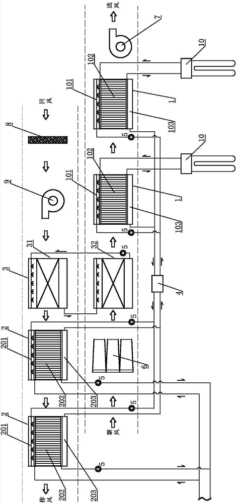
[0049] Such as figure 1 In the schematic diagram of the first embodiment of an internal cooling solution dehumidification unit shown in the present invention, there are two sets of solution dehumidification units 1, two sets of solution regeneration units 2, one set of solution heat recovery units 3, and solution dehumidification units 1 The first solution spraying device 101, the first heat exchange device 102, and the first solution tank 103 are provided in sequence from top to bottom; the solution regeneration unit 2 is provided with a second solution spraying device 201, a second exchange The thermal device 202 , the second solution tank 203 , and the solution heat recovery unit 3 include an upper heat recovery device 31 and a lower heat recovery device 32 with the same structure.

[0050] Between the two sets of solution dehumidification units 1 and the two sets of solution regeneration units 2, a mixed solution dehumidification regeneration loop is arranged through pipel...


PUM


Abstract

The invention relates to an internal-cooled solution dehumidifying assembly. The internal-cooled solution dehumidifying assembly comprises at least one group of solution dehumidifying units, at least one group of solution regeneration units, and at least one group of solution heat recovery units; the solution dehumidifying unit is provided with a first solution spraying device, a first heat exchange device and a first solution box orderly from top to bottom; the solution regeneration unit is provided with a second solution spraying device, a second heat exchange device and a second solution box orderly from top to bottom; the solution heat recovery unit comprises an upper heat recoverer and a lower recoverer, the two of which are the same in structure. A solution dehumidifying regeneration cycle loop is arranged between the solution dehumidifying unit and the solution regeneration unit, while a solution heat recovery cycle loop is arranged between the upper heat recoverer and the lower recoverer; the first heat exchange device and the second head exchange device are of an internal-cooling or internal-heating heat exchange mode. The internal-cooled solution dehumidifying assembly has the advantages of stable system, low manufacturing and operating costs, high energy efficiency ratio and accurate control.

Description

technical field [0001] The invention relates to dehumidification equipment in the field of air conditioning, in particular to an internal cooling solution dehumidification unit. Background technique [0002] In the field of air conditioning, it is usually necessary to cool and dehumidify the incoming outdoor air in summer, and to heat and humidify the incoming outdoor air in winter. Most of the traditional air-conditioning systems use condensation dehumidification treatment, that is, use a refrigerator to prepare low-temperature chilled water, and circulate the chilled water in the coil of the surface cooler and exchange heat with the air to reduce the air temperature below the dew point. In this way, the air condenses to dehumidify the fresh air. The dehumidification and cooling process of this treatment method are controlled as one and carried out at the same time. Since the chilled water temperature required for dehumidification is much lower than the chilled water tempe...

Claims


Application Information

Patent Timeline
IPC IPC(8): F24F3/147
CPCF24F3/1417F24F3/147F24F2003/1446
Inventor 丛旭日冯婷婷
Owner 丛旭日
Why Eureka
Try Eureka