Synthetic vision system calibration method based on airborne instrument landing device

A technology for synthetic vision and system verification, which is applied in the field of synthetic vision system verification based on airborne instrument landing equipment, can solve problems such as large errors in angle or attitude verification, improve practicability, improve verification efficiency, The effect of improving the safety of low-altitude flight

Inactive Publication Date: 2015-04-08
NORTHWESTERN POLYTECHNICAL UNIV
View PDF6 Cites 10 Cited by
  • Summary
  • Abstract
  • Description
  • Claims
  • Application Information

AI Technical Summary

Problems solved by technology

[0005] In order to avoid the deficiencies in the prior art, the present invention proposes a method for verifying the synthetic vision system based on airborne instrument landing equipment, using the spatial angle information given by the instrument landing system as The vision system is calibrated; to solve the problem that the existing altitude-based calibration method has a large error in the angle or attitude calibration, effectively improve the usability of the synthetic vision system during the approach phase, and improve the safety of low-altitude flight

Method used


Image

  • Synthetic vision system calibration method based on airborne instrument landing device
  • Synthetic vision system calibration method based on airborne instrument landing device
  • Synthetic vision system calibration method based on airborne instrument landing device

Examples


Embodiment Construction

[0024] This embodiment is a method for verifying a synthetic vision system based on an airborne instrument landing equipment.

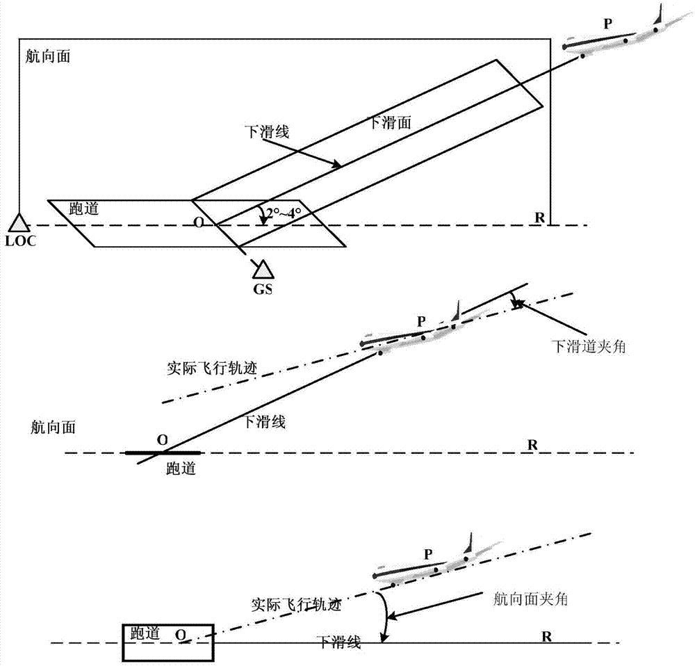
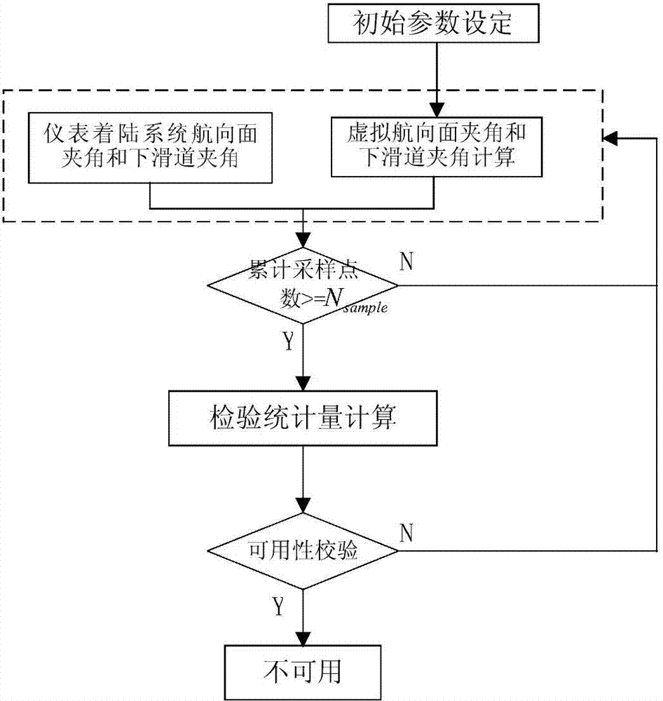
[0025] refer to figure 1 , figure 2 , image 3 , the present embodiment is based on the synthetic visual system verification method of the airborne instrument landing equipment, and the specific steps are as follows:

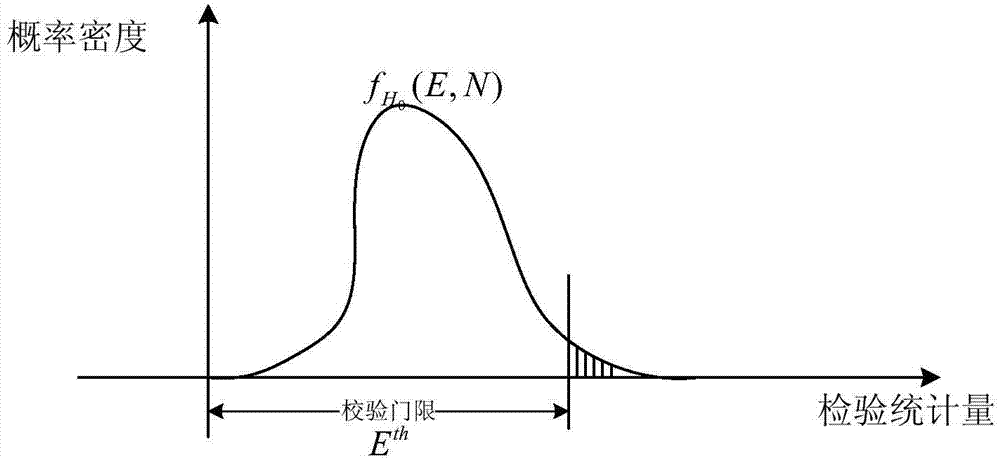
[0026] The first step is to set the parameters used for verification of the synthetic vision system, including: verification sampling time T sample , check the number of single sampling points N sample , check threshold E th ; T sample The calibration sampling time should be determined by the time interval T of the included angle data output by the instrument landing system ILS , synthetic vision system update time interval T SVS Determine, take the least common multiple of two values;

[0027] N sample Check the maximum alarm time T given by the synthetic vision system in advance for the number of single sampling points warn...


PUM


Abstract

The invention discloses a synthetic vision system calibration method based on an airborne instrument landing device. The method comprises the following steps: calibrating a synthetic vision system at an approach stage by adopting spatial angle information given by an instrument landing system as a reference system; determining a calibration sampling time, calibrating a single-time sampling number, and calibrating the threshold; acquiring a course surface included angle and a lower slide-way angle obtained by the synthetic vision and instrument landing system in real time in the approach process; calculating calibration statistics by adopting the acquired included angle data; carrying out the availability calibration for the synthetic vision system by utilizing the calculated calibration statistics. By adopting the method, the weakness of the traditional method for calibrating the airport characteristic synthetic vision display availability can be overcome, the capacity for calibrating the altitude or angle information situation of the synthetic vision system can be improved, and the calibration efficiency for the updating of the synthetic vision caused by little change of the altitude of an airplane in the calibration process can be improved; the practicability of the synthetic vision system at the approach stage can be effectively improved, and the security of the low altitude flight can be improved.

Description

technical field [0001] The invention relates to a verification method in the actual application process of a synthetic vision system, in particular to a verification method of a synthetic vision system based on an airborne instrument landing device during an aircraft approach. Background technique [0002] Faced with the complex terrain and meteorological environment encountered by the aircraft during flight, in order to enable pilots to perceive the external environment in real time and ensure flight safety, it is necessary to use information perception, image processing and other technologies to present the surrounding environment of the aircraft. Based on the attitude of the aircraft, high-precision navigation, terrain database, obstacles and other related technologies, the synthetic vision system uses computer-generated forward virtual vision as an aid to traditional instruments to help pilots "see" the flying environment around them, Reduce workload. [0003] The synth...

Claims


Application Information

Patent Timeline
Patent Type & Authority Applications(China)
IPC IPC(8): G01C25/00
CPCG01C25/00
Inventor 宋东马存宝陈杰沈春南和麟张天伟
Owner NORTHWESTERN POLYTECHNICAL UNIV
Why Eureka
Try Eureka