Valve air tightness detection system

A technology for air tightness detection and valves, which is applied in the direction of liquid tightness measurement by using liquid/vacuum degree, and by detecting the appearance of fluid at the leakage point, etc. The test conditions of the test valves are consistent, the test results are easily affected, etc., to achieve the effect of consistent test conditions, convenient operation, and consistent opening angle

CN104502030BActive Publication Date: 2017-06-16RIFENG ENTERPRISE GRP CO LTD +1
6 Cites 0 Cited by

Patent Information

Authority / Receiving Office
CN · China
Patent Type
Patents(China)
Current Assignee / Owner
Publication Date
2017-06-16

Smart Images

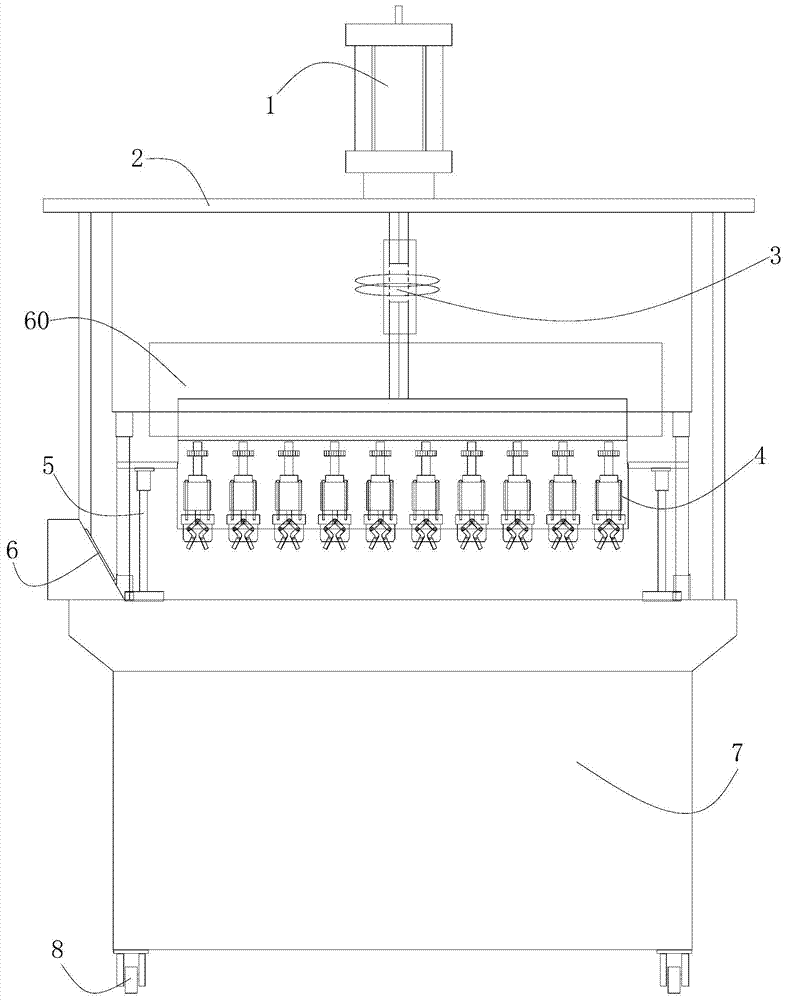
  • Figure 1
    Figure 1
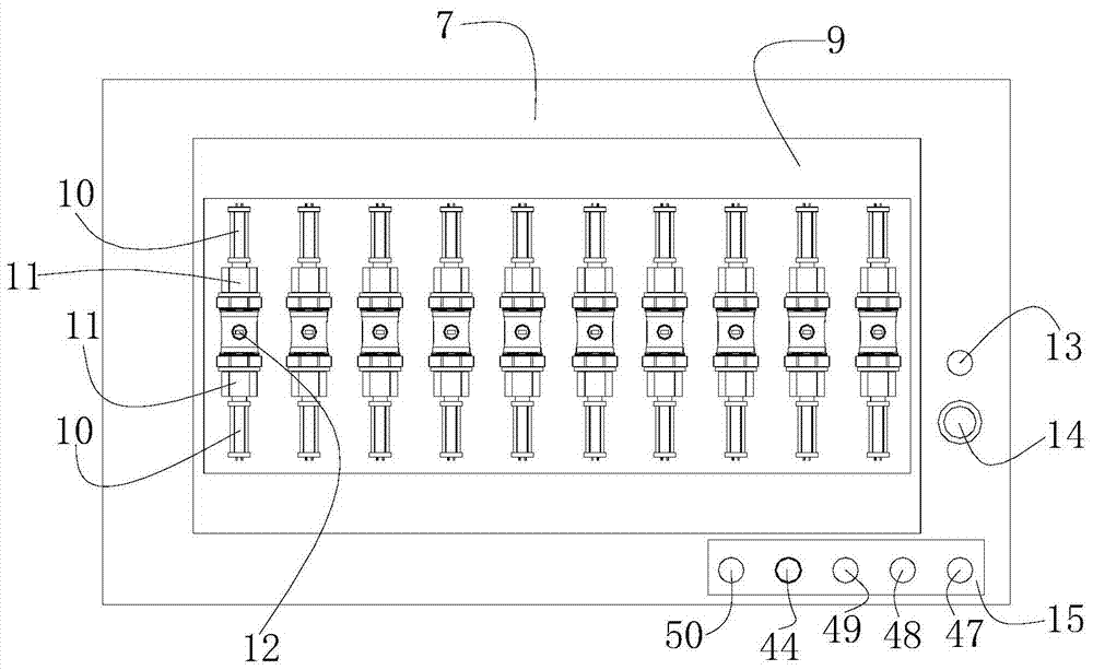
  • Figure 2
    Figure 2
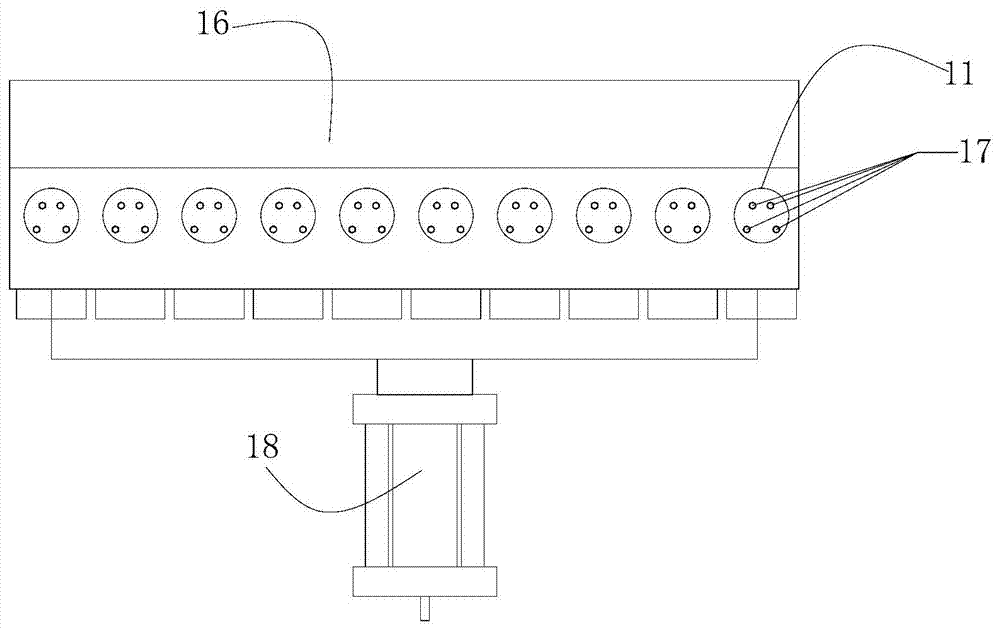
  • Figure 3
    Figure 3
Patent Text Reader

Abstract

The invention discloses a detection system for air tightness of a valve. The system comprises a water tank, a water tank bracket, upper and lower pneumatic cylinders, a manipulator bracket, a plurality of manipulators and a manipulator transmission mechanism, wherein a water channel, a water inlet cylinder and a plurality of valve clamping fixtures are arranged in the water tank; the valve clamping fixtures are connected with the water inlet cylinder; the water tank bracket is fixedly arranged on the upper side of the water tank; the upper and lower pneumatic cylinders are arranged on the water tank bracket; the manipulator bracket is connected with piston rods of the upper and lower pneumatic cylinders; the manipulators are ranged on the manipulator bracket; each manipulator comprises a main shaft, a manipulator cylinder, a manipulator clamp and two clamping arms; the main shafts are provided with transmission gears; the manipulator cylinders are connected with the main shafts; the manipulator clamps are fixedly connected with the manipulator cylinders; the clamping arms are hinged in the manipulator clamps; one end of each clamping arm is hinged to the piston rod of the manipulator cylinder through a connecting arm respectively; the manipulator transmission mechanism comprises a transmission cylinder and a rack which is fixedly connected to the transmission cylinder; each transmission gear is engaged with the rack. The system can realize that the opening angle of a to-be-tested valve at each station is consistent to guarantee consistent testing condition of each to-be-tested valve and further achieve a more accurate test result.
Need to check novelty before this filing date? Find Prior Art

Description

technical field

[0001] The invention mainly relates to the field of valve air tightness detection, in particular to the technical field of valve air tightness detection system. Background technique

[0002] The sealing performance of the valve is a very important function of the quality of the valve. Almost all valve product standards regard the air tightness of the valve as a very important inspection and control item. When testing the airtightness of the valve, it includes shell test, upper seal test and sealing test. Among them, the method and steps of the shell test are: close both ends of the flow channel of the valve to be tested, press the packing gland, make the valve to be tested partially open and put it into water, inflate the valve body to be tested and gradually pressurize it After reaching the test pressure and reaching the specified time, check whether there is any penetration in the shell. The existing testing machine for valve shell test includes a water t...

Examples

Embodiment Construction

[0026] Such as Figure 1-7 As shown, the valve airtightness detection system of the present invention comprises a water tank 7, a water tank support 2 fixed on the top of the water tank 7, an upper and lower pneumatic cylinder 1 on the water tank support 2, and a piston rod end connected with the upper and lower pneumatic cylinder 1. The manipulator bracket 60, several manipulators 4 arranged on the manipulator support 60 and respectively corresponding to the manipulator 4 above the valve 12 to be tested, and the manipulator transmission mechanism connected with each manipulator 4. The water tank 7 is provided with a water tank 9, a water inlet cylinder 18, and a plurality of valve clamping fixtures 11 that can close the two ends of the flow channel of the valve to be tested 12. A fixture bracket 16 is connected above the water inlet cylinder 18, and a plurality of valve clamping fixtures 11 are arranged side by side. Set on the fixture bracket 16, the clamping end of the valv...