On-line visual detection system for LED luminosity

A visual detection and luminance technology, applied in photometry, measuring device, optical radiation measurement, etc., can solve the problems of large error, inability to meet detection requirements, and low efficiency.

Inactive Publication Date: 2019-01-18
惠州西电仲恺人工智能联合创新实验室有限公司
View PDF6 Cites 0 Cited by
  • Summary
  • Abstract
  • Description
  • Claims
  • Application Information

AI Technical Summary

Problems solved by technology

In the traditional LED lamp diffraction panel luminance detection, the luminance of the diffraction panel irradiated by the detector is often manually discriminated and detected. However, the efficiency of manual detection is low, the error is large, the procedure is complicated, and it cannot meet the requirements of large-scale LED production. The detection requirements under

Method used


Image

  • On-line visual detection system for LED luminosity
  • On-line visual detection system for LED luminosity
  • On-line visual detection system for LED luminosity

Examples


Embodiment Construction

[0027] In order to make the object, technical solution and advantages of the present invention clearer, the present invention will be further described in detail below in conjunction with the accompanying drawings and embodiments. It should be understood that the specific embodiments described here are only used to explain the present invention, not to limit the present invention.

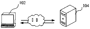
[0028] The method in the LED luminance online visual detection system provided in the embodiment of the present invention can be applied to such as figure 1 shown in the application environment. Wherein, the terminal 102 communicates with the server 104 through the network. The server 104 sends to the terminal 102 an instruction to obtain several test areas on the diffraction panel to be tested, and after receiving the instruction to obtain several test areas on the diffraction panel to be tested, the terminal 102 responds within the first preset time and gives feedback The location information o...


PUM


Abstract

The invention relates to an on-line visual detection system for LED luminosity. Luminosity detection is conducted on an LED diffraction panel through a scientific detection method to ensure that the light intensity of the whole lamp strip or the lamp surface of the LED diffraction panel is kept consistent. According to an LED diffraction panel luminosity detection method, a plurality of test areasare obtained from the LED diffraction panel, luminosity absolute values of all the test areas are obtained, the luminosity absolute value of one of the test areas is selected to be subjected to difference value calculation with the luminosity absolute values of the remaining test areas, and a plurality of obtained difference values are compared with a preset difference value; and if the multipledifference values are all less than the preset difference value, it is proved that the overall light intensity of the LED diffraction panel is consistent basically, and the detected LED diffraction panel is qualified, and otherwise, the detected LED diffraction panel is unqualified. The LED diffraction panel luminosity detection method is scientific and reasonable, under computer equipment controldetection, the detection time is short, the detection efficiency is high, the error is low, and the detection demands under LED mass production are met.

Description

technical field [0001] The invention relates to the field of LED (Light Emitting Diode, light emitting diode) brightness detection, in particular to an LED brightness online visual detection system. Background technique [0002] LED, light-emitting diode is a solid-state semiconductor device that can directly convert electrical energy into light energy. LED energy saving, low cost, its high luminous efficiency is twice that of ordinary fluorescent lamps; LED has a long service life, and the service life of LED with better performance can reach 50,000 hours; LED components have simple structure, good impact resistance and shock resistance, and are not easy to break Can be well adapted to various environments; LED lights have low brightness attenuation, and the light brightness attenuation is much lower than that of halogen lamps. Due to the many advantages of LED lamps over ordinary fluorescent lamps, they are widely used in various fields of life. Luminance is used to de...

Claims


Application Information

Patent Timeline
IPC IPC(8): G01J1/00
CPCG01J1/00
Inventor 吴楚林田政权戴浩鹏
Owner 惠州西电仲恺人工智能联合创新实验室有限公司
Why Eureka
Try Eureka