Controllable strake wing/canard wing pitching angle movement system of airplane wind tunnel test model
A wind tunnel test, slatted wing technology, used in aerodynamic tests, machine/structural component testing, control using feedback, etc., to achieve the effect of rudder surface action or active flow control
- Summary
- Abstract
- Description
- Claims
- Application Information
AI Technical Summary
Problems solved by technology
Method used
Image
Examples
Embodiment 1
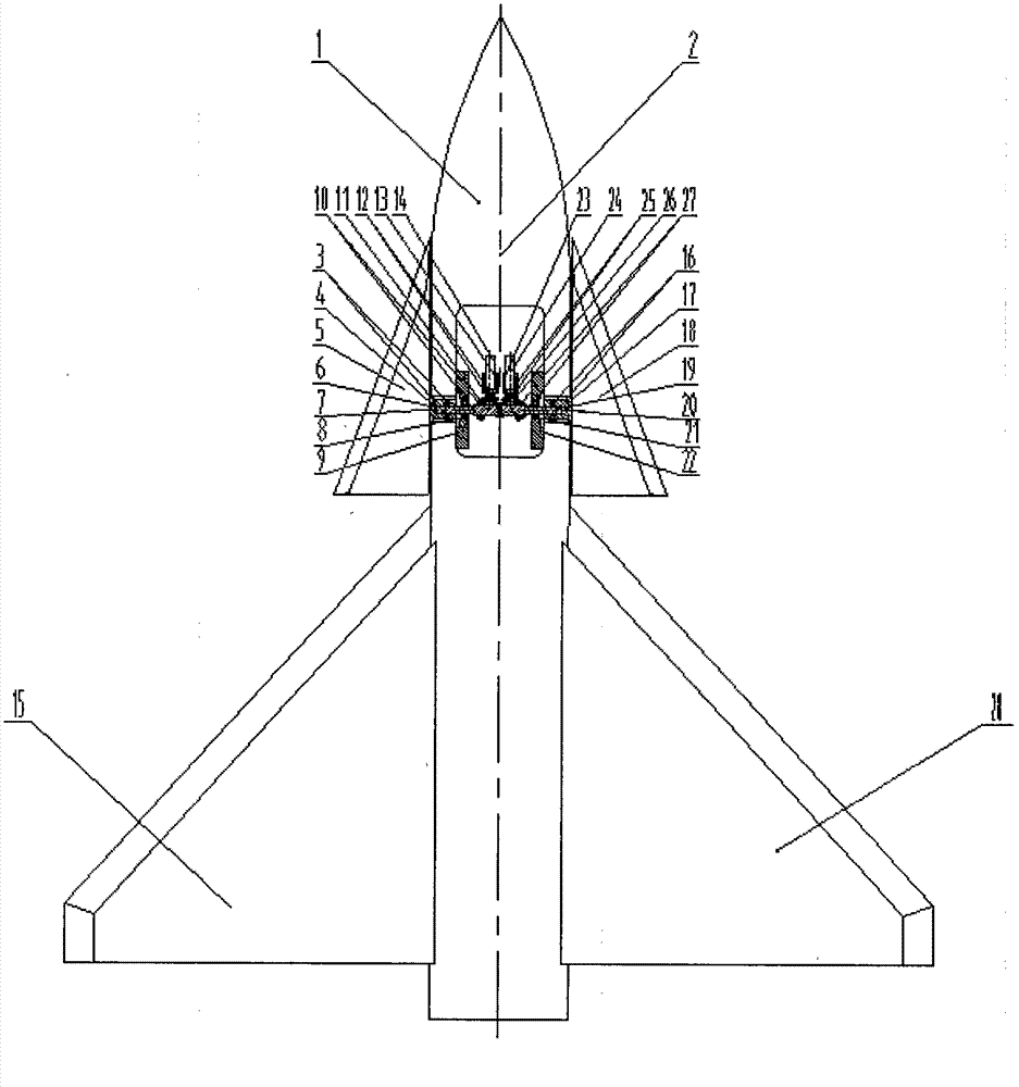
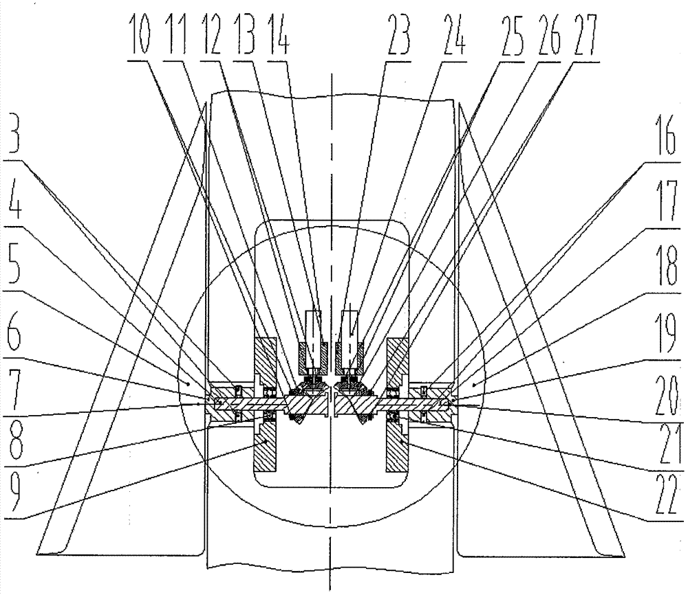
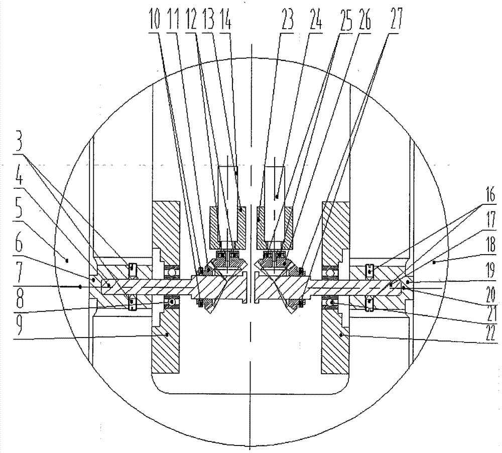
[0023] Such as figure 1 As shown, an aircraft wind tunnel test model side strip wing / canard pitch angle controllable motion system includes a fuselage head assembly 1, an aircraft model body shaft system longitudinal axis 2, a first left locking screw 3, a left connecting Shaft 4, left wing / canard 5, left wing / canard rotating shaft 6, left bearing 8, left bearing seat 9, second left locking screw 10, left reversing bevel gear pair 11, third left locking Screw 12, left motor mounting seat 13, left motor and encoder 14, left main wing 15, first right locking screw 16, right connecting shaft 17, right strip wing / canard wing 18, right strip wing / canard wing shaft 19, Right bearing 21, right bearing seat 22, right motor mount 23, right motor and encoder 24, third right locking screw 25, right reversing bevel gear pair 26, second right locking screw 27, right main wing 28, Computer 29, left motor driver 30 and right motor driver 31; Left main wing 15, right main wing 28, left beari...
Embodiment 2
[0026] There are three methods for the deflection control commands of the left and right side bars:
[0027] (1) The stepped deflection control command can realize the stepwise change of the pitch angle of the side strip wing / canard wing, that is, the static adjustment of the pitch angle angle, which is used for static tests;
[0028] (2) Uniform speed motion control command, which can adjust the displacement and speed of the movement, and can realize the uniform speed change of the pitch angle of the wing / canard, which can be used in the dynamic deflection test to test the dynamic effect of the deflection of the side strip, that is, to dynamically adjust the pitch In addition, the beneficial interference of the aerodynamic vortex system of the side wing / canard wing and the aerodynamic vortex system of the main wing can be obtained, thereby realizing active flow control or equivalent to the role of the rudder surface, and improving the aerodynamic characteristics of the aircraf...
Embodiment 3
[0031] There are five methods of synchronous / asynchronous control commands for the left wing / canard 5 and the right wing / canard 18:
[0032] (1) Left wing / canard 5 or right wing / canard 18 individual deflection control command, used to realize the left wing / canard 5 or right wing / canard 18 individually controllable deflection;
[0033] (2) The same-phase synchronous deflection control command of the left wing / canard 5 and the right wing / canard 18 is used to realize the same-phase synchronous controllable control of the left wing / canard 5 and the right wing / canard 18 deflection;
[0034] (3) The opposite phase of the left wing / canard 5 and the right wing / canard 18, that is, the 180° phase difference synchronous deflection control command, is used to realize the left wing / canard 5 and the right wing / canard 18 The anti-phase synchronous controllable deflection of ;
[0035] (4) Any phase difference synchronous deflection control command of the left strip / canard 5 and the right s...
PUM
 Abstract
Description
Claims
Application Information
 - R&D
- Intellectual Property
- Life Sciences
- Materials
- Tech Scout
- Unparalleled Data Quality
- Higher Quality Content
- 60% Fewer Hallucinations
Browse by: Latest US Patents, China's latest patents, Technical Efficacy Thesaurus, Application Domain, Technology Topic, Popular Technical Reports.
© 2025 PatSnap. All rights reserved.Legal|Privacy policy|Modern Slavery Act Transparency Statement|Sitemap|About US| Contact US: help@patsnap.com


