Controllable Motion System of Dihedral Angle in Aircraft Wind Tunnel Test Model
A technology of wind tunnel test and motion system, applied in aerodynamic test, machine/structural component test, measuring device, etc.
- Summary
- Abstract
- Description
- Claims
- Application Information
AI Technical Summary
Problems solved by technology
Method used
Image
Examples
Embodiment 1
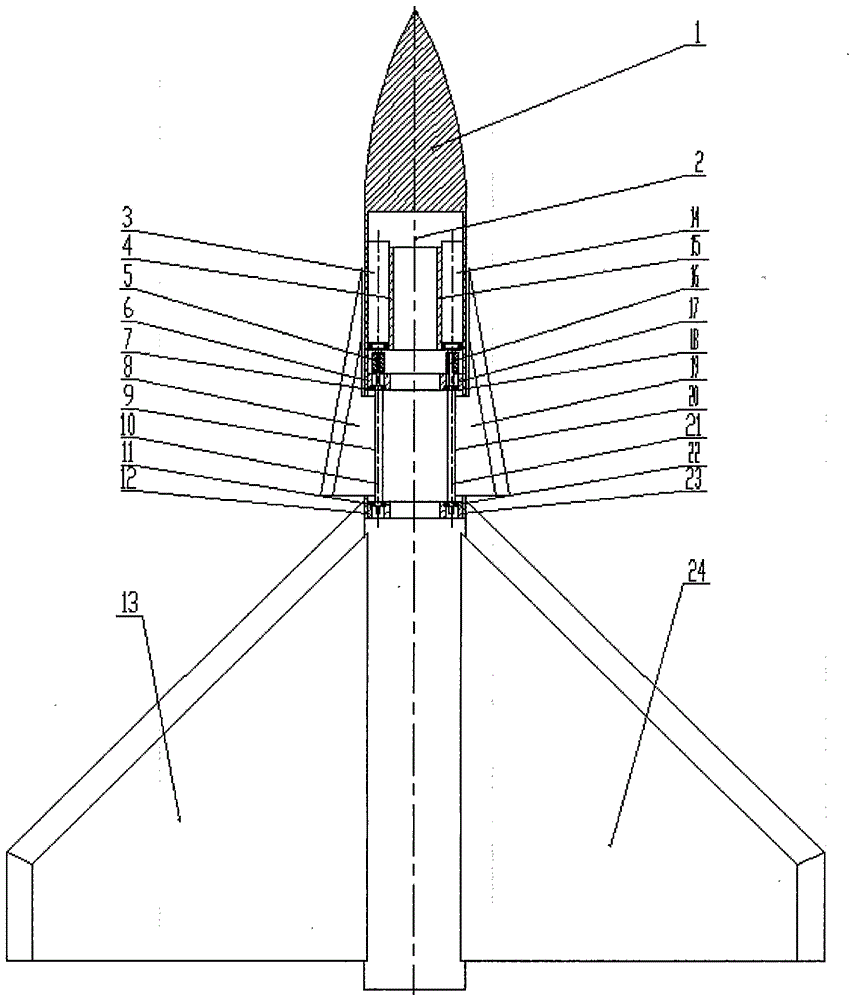
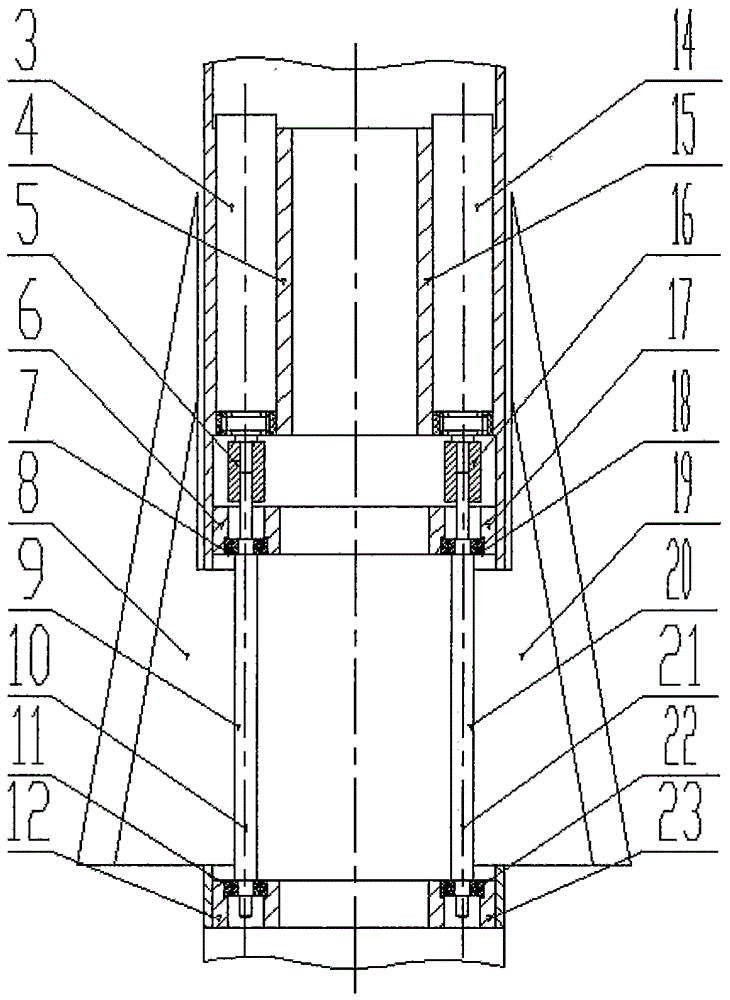
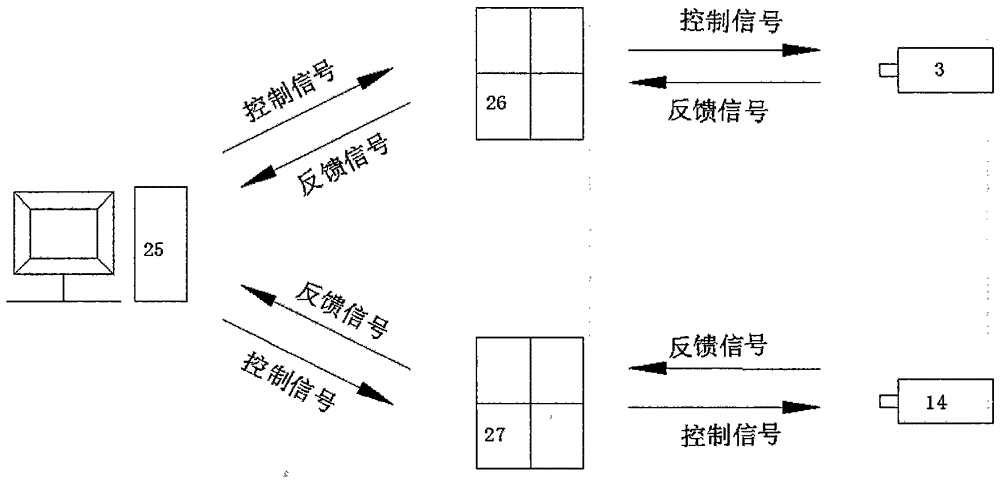
[0020] Such as figure 1 As shown, an aircraft wind tunnel test model dihedral dihedral controllable motion system includes fuselage head assembly 1, aircraft model body shaft longitudinal axis 2, left motor and encoder 3, left motor mounting seat 4 , left coupling 5, left front bearing housing 6, left front bearing 7, left wing 8, left wing shaft 9, left wing shaft axis 10, left rear bearing 11, left rear bearing housing 12, left main wing 13, right Motor and encoder 14, right motor mount 15, right coupling 16, right front bearing seat 17, right front bearing 18, right wing 19, right wing shaft 20, right wing shaft axis 21, right rear bearing 22, Right rear bearing seat 23, right main wing 24, computer 25, left motor driver 26 and right motor driver 27, computer 25 is connected with left motor driver 26 and right motor driver 27 electric signals respectively, left motor driver 26 is connected with left motor and encoder 3 electrical signal connection, right motor driver 27 is...
Embodiment 2
[0023] The deflection control commands of the left wing 8 and the right wing 19 can be:
[0024] (1) The stepped deflection control command can realize the stepwise change of the dihedral angle of the side strip, that is, the static adjustment of the dihedral angle, which is used in static tests; The speed runs to the specified position.
[0025] (2) Uniform motion control command, the angular displacement and speed of the motion can be adjusted, which can realize the uniform speed change of the dihedral angle of the side strip, which can be used in the dynamic deflection test to test the dynamic effect of the side strip deflection, that is, to dynamically adjust the dihedral angle. In addition, the beneficial interference of the aerodynamic vortex system of the side wing and the aerodynamic vortex system of the main wing can be obtained, so as to realize active flow control or equivalent to the role of the rudder surface, and improve the aerodynamic characteristics of the air...
Embodiment 3
[0028] The synchronous / asynchronous control instructions of the left wing 8 and the right wing 19 can be:
[0029] 1. The left side wing 8 or the right side wing 19 deflection control command alone, which is used to realize the left side wing 8 or the right side wing 19 individually controllable deflection; the implementation method is to directly send instructions to the left side wing 8 or the right side wing 19 .
[0030] 2. The same-phase synchronous deflection control command of the left wing 8 and the right wing 19 is used to realize the same-phase synchronous controllable deflection of the left wing 8 and the right wing 19; The right wing 19 sends the same command.
[0031] 3. The opposite phase of the left wing 8 and the right wing 19, that is, the 180° phase difference synchronous deflection control command, is used to realize the anti-phase synchronous controllable deflection of the left wing 8 and the right wing 19; its embodiment is Simultaneously send instructio...
PUM
 Abstract
Description
Claims
Application Information
 - R&D
- Intellectual Property
- Life Sciences
- Materials
- Tech Scout
- Unparalleled Data Quality
- Higher Quality Content
- 60% Fewer Hallucinations
Browse by: Latest US Patents, China's latest patents, Technical Efficacy Thesaurus, Application Domain, Technology Topic, Popular Technical Reports.
© 2025 PatSnap. All rights reserved.Legal|Privacy policy|Modern Slavery Act Transparency Statement|Sitemap|About US| Contact US: help@patsnap.com


