
Method for qualifying liquid loading of gas well

A technology for effusion and gas wells, applied in data processing applications, instruments, calculations, etc., to achieve the effects of simple testing, avoiding misjudgment, and improving accuracy

Inactive Publication Date: 2015-04-08
CHINA UNIV OF GEOSCIENCES (WUHAN)
View PDF2 Cites 15 Cited by
  • Summary
  • Abstract
  • Description
  • Claims
  • Application Information

AI Technical Summary

Problems solved by technology

[0005] The purpose of the present invention is to solve the problems in the existing wellbore fluid identification process, further improve the accuracy of wellbore fluid identification, and provide a method for qualitatively determining whether the wellbore of a gas well has fluid accumulation

Method used


Image

  • Method for qualifying liquid loading of gas well
  • Method for qualifying liquid loading of gas well
  • Method for qualifying liquid loading of gas well

Examples


Embodiment 1

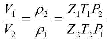
[0038] Example 1: The vertical depth from the bottom of the well to the wellhead is 5000m, the bottomhole pressure is 35MPa, the bottomhole temperature is 414.15K, and the gas deviation coefficient is 0.78; the wellhead pressure is 3.3MPa, the wellhead temperature is 284.2K, the corresponding gas deviation coefficient is 0.8965, and the gas density at the wellhead condition is 30.3745kg / m 3 , the density of condensate oil is 793kg / m 3 , the formation water density is taken as 1078kg / m 3 . Substitute the above parameters into the material balance (equation of state) model to obtain the gas density at the bottom hole condition.

[0039] Table 1

[0040]

pressure, MPa

temperature, K

Volume Variation Coefficient

Gas density, kg / m 3

known conditions

3.3

284.2

0.8965

30.3745

Bottomhole condition

35

414.15

0.78

254.0887

[0041] In Table 1, the known gas density is the gas density at the wellhead ...


PUM


Abstract

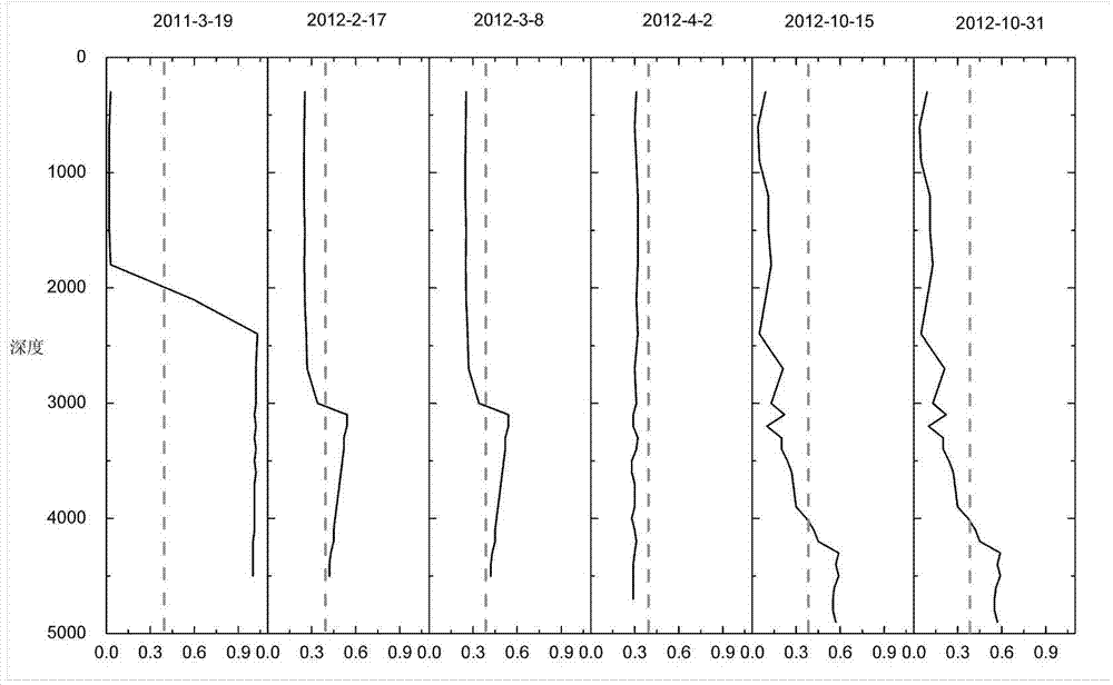
The invention discloses a method for qualifying liquid loading of a gas well for use in the development process of gas reservoirs and condensate gas reservoirs. Corresponding oil-water ratios at different time are calculated with daily production data of the gas well in order to obtain corresponding critical pressure gradients, and the critical pressure gradients are compared with a pressure gradient test curve for analysis. If the maximum value of the test pressure gradient curve surpasses the critical pressure gradient value, liquid loading in a shaft occurs; on the contrary, if the maximum pressure gradient value is lower than critical pressure gradient values, liquid loading does not exist in the shaft even the pressure gradient curve fluctuates. Critical pressure gradients under different oil-water ratio conditions are calculated through a substance balance state equation model and a critical pressure gradient model by using daily test data of the gas reservoirs and condensate gas reservoirs, and the critical pressure gradients are compared with the pressure gradient curve to judge whether liquid loading occurs in the shaft or not, so that various errors caused by direct manual qualitative analysis are avoided, and the accuracy of liquid loading judgment is increased.

Description

technical field [0001] The invention relates to the technical field of mining, in particular to a method for characterizing fluid accumulation in gas well bores during oil and gas well development. Background technique [0002] In the process of oil and gas reservoir development, the core goal of evaluating its development effect and carrying out production measures is to improve its recovery factor. Among the methods of enhancing oil recovery, the most time-saving, labor-saving and cost-saving method is to increase the cumulative oil and gas production of a single well while keeping the existing development mode unchanged. [0003] For gas wells and condensate gas wells, how to accurately judge whether the wellbore has fluid accumulation and the time of fluid accumulation is the core issue for reasonable production adjustments and measures in the later stage, and prolonging the production time of a single well (thus increasing the cumulative oil and gas production of a sing...

Claims


Application Information

Patent Timeline
Patent Type & Authority Applications(China)
IPC IPC(8): G06Q50/02G06Q50/06
CPCG06Q50/02G06Q50/06
Inventor 潘琳李龙龙李宗宇关闻梁静献
Owner CHINA UNIV OF GEOSCIENCES (WUHAN)
Learn More