Ethernet transmission circuit

A transmission circuit and Ethernet technology, applied in the field of Ethernet communication, can solve problems such as short single-line transmission distance, low signal stability, and weak drive capability of conversion chips, so as to improve isolation and compatibility, improve networking speed, The effect of enhancing stability

Inactive Publication Date: 2015-04-08
李钢
View PDF4 Cites 4 Cited by
  • Summary
  • Abstract
  • Description
  • Claims
  • Application Information

AI Technical Summary

Problems solved by technology

However, in the current Ethernet communication circuit, because it is directly connected to the RJ interface, and the driving ability of the conversion chip is not strong, the signal stability is low
The single-line tra

Method used


Image

  • Ethernet transmission circuit

Examples


Embodiment Construction

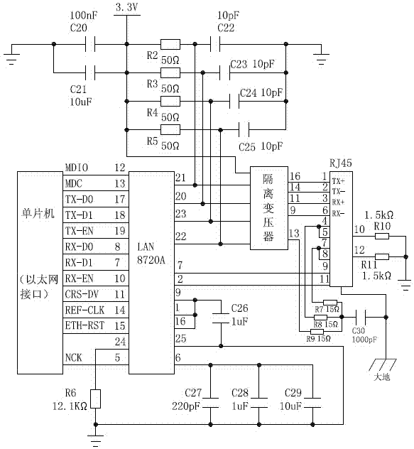
[0010] like figure 1 The Ethernet transmission circuit shown includes the chip LAN8720A, the 24th pin of the chip LAN8720A is grounded through the resistor R6, the 6th pin of the chip LAN8720A is grounded through the capacitor C27, the capacitor C28 and the capacitor C29 are respectively connected in parallel with the capacitor C27, and the 1st pin of the chip LAN8720A The 25th pin is grounded, the first pin of the chip LAN8720A is grounded through the capacitor C26, the 9th pin and the 16th pin of the chip LAN8720A are respectively connected to the first pin of the chip LAN8720A, and the 21st pin of the chip LAN8720A is respectively connected to the resistor R2 One end and one end of capacitor C22, the other end of resistor R2 is connected to 3.3V voltage, the other end of capacitor C22 is grounded, the 20th pin of chip LAN8720A is connected to one end of resistor R3 and one end of capacitor C23 respectively, the other end of resistor R3 is connected to 3.3V voltage, and the o...


PUM


Abstract

The invention discloses an Ethernet transmission circuit. The Ethernet transmission circuit comprises a protocol conversion chip LAN8720A, an isolating transformer and an RJ45 interface, wherein the protocol conversion chip LAN8720A is connected with a filter circuit; an input end of the isolating transformer is connected with a pull-up resistor and a 3.3V power supply; an EMC (Electro Magnetic Compatibility) boosting circuit is arranged between the isolating transformer and the RJ45 interface; a protocol conversion chip LAN8720A filter network consisting of C22, C23, C24, C25, C26, C27, C28 and C29 is arranged, a drive capacity enhancement network consisting of R2, R3, R4 and R5 is arranged, a compatibility enhancement network consisting of R7, R8, R9 and R30 is arranged, and the effect of the isolating effect is combined, so the isolation and the compatibility are improved, the networking speed is improved, and the stability for work of an Ethernet unit is greatly enhanced.

Description

technical field [0001] The invention relates to the field of Ethernet communication, in particular to an Ethernet transmission circuit. Background technique [0002] In industrial control, it is currently the most important communication mode to realize the data and command communication between the control equipment and the upper computer by means of Ethernet (Interet). However, in the current Ethernet communication circuit, since it is directly connected to the RJ interface and the driving capability of the conversion chip is not strong, the stability of the signal is relatively low. The single-line transmission distance is short and, due to the industrial environment, the equipment operates in an electromagnetic environment, which also puts forward new requirements for the EMC compatibility of Ethernet communication. Contents of the invention [0003] In order to solve the above problems, the present invention provides an Ethernet transmission circuit, which not o...

Claims


Application Information

Patent Timeline
IPC IPC(8): H04L12/02H03H7/01
Inventor 李钢
Owner 李钢
Why Eureka
Try Eureka