continuous casting method for steel

A technology of casting speed and cast slabs, which is applied in the field of continuous casting of steel, can solve the problems of unspecified solidified shell thickness, unstable cast slab shape, and unimproved center segregation, so as to improve center segregation, increase reduction efficiency, reduce The effect of center segregation

Active Publication Date: 2017-03-08
JFE STEEL CORP
View PDF10 Cites 0 Cited by
  • Summary
  • Abstract
  • Description
  • Claims
  • Application Information

AI Technical Summary

Problems solved by technology

[0020] That is, in Patent Documents 3 to 5, when the slab is intentionally expanded, the thickness of the solidified shell of the slab before expansion is not specified, and therefore, when the expansion start timing is too early, there may be occurrence of The risk of fracture caused by cracks and swelling
In addition, in Patent Documents 3 to 5, the expansion application speed when the slab is intentionally expanded is not predetermined. Therefore, in the case of rapid expansion, internal cracks occur in the expanded solidified shell, and when the internal cracks are severe , there is also a risk of fracture
[0021] In addition, in Patent Documents 3 to 5, the expansion region and the reduction region are continuously provided in the continuous casting machine, and the slab is expanded immediately after the reduction. Therefore, the shape of the expanded slab is unstable, and there are also problems caused by casting. Depending on the position of the sheet, the pressing force is not transmitted to the center of the thickness of the cast sheet, and the center segregation is not improved.

Method used


Image

  • continuous casting method for steel
  • continuous casting method for steel
  • continuous casting method for steel

Examples


Embodiment 1

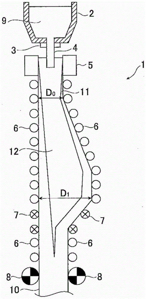
[0096] use figure 1 In the shown continuous slab caster, a test was carried out using the first embodiment of the present invention in which the cast slab was intentionally expanded and then pressed down. The width of the cast sheet is 2100mm, and the thickness of the cast sheet before the expansion starts (D 0) is 250mm. In addition, the casting speed is 0.85m / min to 1.2m / min, and the specific water quantity for secondary cooling of the cast sheet is 1.0 to 2.0 liters / steel-kg. The total amount of intentional expansion is 3.0mm to 21.0mm. The thickness of the solidified shell before expansion, the gradient of the roll opening during expansion, the casting direction length of the section where the thickness of the slab after expansion is constant (the section where the roll opening of the guide roll is set to be constant), and the pressure Experiments were carried out in various ways of changing the total amount. The cast steel grade is a steel grade for thick steel plates...

Embodiment 2

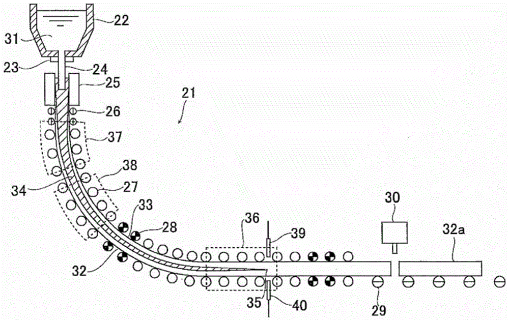
[0110] use figure 2 The slab continuous casting machine of the shown structure implemented the test which applied the 2nd embodiment of this invention and performed casting (this invention example: test number 21-25). A slab cast slab for a thick steel plate was cast with a width of 2100 mm, a thickness of 250 mm directly below the mold, and a carbon content of 0.05 to 0.08 mass %. The casting speed is 0.85-1.42m / min, and the specific water volume for secondary cooling of the casting sheet is 1-2 liters / steel-kg.

[0111] The total reduction of the short-side width narrowed reduction zone is 3.0 mm to 20.0 mm, and the total expansion of the intentional expansion zone is 3.0 mm to 20.0 mm. In addition, the total reduction of the light reduction zone is the same as the total expansion or below. In addition, the solid fraction at the central portion of the slab thickness at the end of the light reduction is 0.9 or more.


PUM

PropertyMeasurementUnit
thicknessaaaaaaaaaa
thicknessaaaaaaaaaa
thicknessaaaaaaaaaa

Abstract

A slab is continuously cast in such a manner that the slab is intentionally bulged and thereafter the slab having an unsolidified layer is compressed under conditions controlled to prevent the bulging from causing a breakout of the slab and from causing internal cracks in a solidified shell of the slab to reduce central segregation in the slab and positive segregation near a core portion of the slab. A slab 10 is guided on slab-supporting rolls 6 disposed with constant roll gaps from immediately below a casting mold to a point where the thickness of a solidified shell 11 of the slab reaches 15 mm. Thereafter, the slab is bulged on rolls disposed with gradually increased roll gaps with a total amount of bulging of 3 to 20 mm, and is thereafter guided on rolls disposed with constant roll gaps in a zone 0.5 to 5.0 m in length toward the downstream in the casting direction. Subsequently, when the solid phase fraction in a core portion of the slab is from 0.2 to 0.9, the slab is compressed by at least one pass through reduction rolls 7 under such conditions that the product of the compressing rate multiplied by the casting speed is 0.3 to 1.0 mm·m / min 2 .

Description

technical field [0001] The present invention relates to intentional expansion in such a way that the cast sheet drawn from the mold does not breakout and does not create internal cracks, after which, the reduction of the cast sheet in continuous casting with an unsolidified layer is reduced. Method of central segregation. Background technique [0002] In continuous casting of steel, molten steel is poured into a water-cooled mold for cooling (called "primary cooling"), thereby forming a solidified shell on the inner wall of the mold. Then, the slab is continuously drawn downward while being supported by the solidified shell as an outer shell by a plurality of slab support rolls installed below the mold. In this drawing process, the surface of the slab is cooled by spray cooling water or the like (called "secondary cooling"), and after the thickness center of the slab is completely solidified, the slab is cut into a predetermined length, and the Manufacture of cast steel. ...

Claims


Application Information

Patent Timeline
Patent Type & Authority Patents(China)
IPC IPC(8): B22D11/128B22D11/16B22D11/20
Inventor 荒牧则亲大野浩之田和聪典五十川彻外石圭吾三木祐司
Owner JFE STEEL CORP
Why Eureka
Try Eureka