Sheet conveying device and image forming apparatus

A technology for conveying devices and sheets, applied in printing devices, transportation and packaging, thin material handling, etc., can solve the problems of reduced charging efficiency, affecting conveyor belt drive, and reduced sheet adsorption force, so as to suppress the impact and prevent floating. effect

Active Publication Date: 2015-04-15
KYOCERA DOCUMENT SOLUTIONS INC
View PDF8 Cites 9 Cited by
  • Summary
  • Abstract
  • Description
  • Claims
  • Application Information

AI Technical Summary

Problems solved by technology

[0005] However, the floating that occurs on the sheet conveyed by the conveyor belt is likely to occur at the corner of the sheet.
On the other hand, in a high-humidity environment or after an image is formed on a sheet using ink, since the resistance of the sheet becomes low, the charging efficiency decreases, and there is a problem that the adsorption force of the sheet due to electrostatic adsorption decreases.
Therefore, in the configuration in which the ends in the width direction of the sheet are attracted by electrostatic attraction, there is a problem that the corners of the sheet cannot be suppressed from floating.
In addition, in the configuration of suction and adsorption using a plurality of belt openings formed on the entire conveyor belt, the suction force of the conveyor belt to the conveyor plate is relatively large depending on whether or not a sheet is placed on the conveyor belt or the size of the sheet. Large changes, so there are problems affecting the drive of the conveyor belt

Method used


Image

  • Sheet conveying device and image forming apparatus
  • Sheet conveying device and image forming apparatus
  • Sheet conveying device and image forming apparatus

Examples


no. 1 approach

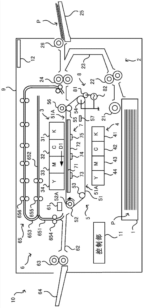
[0024] First, refer to figure 1 A schematic configuration of the image forming apparatus 10 according to the first embodiment of the present invention will be described.

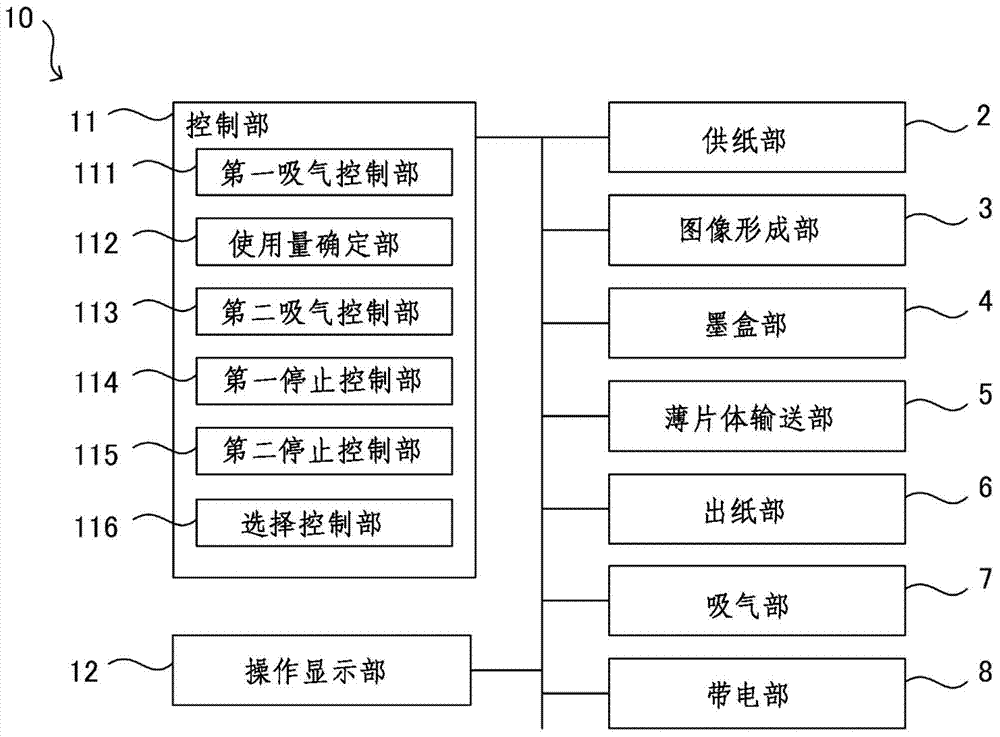
[0025] The image forming apparatus 10 includes: a paper feeding cassette 1 , a paper feeding unit 2 , an image forming unit 3 , an ink cartridge unit 4 , a sheet conveying unit 5 , a paper discharge unit 6 , an air suction unit 7 , a charging unit 8 , and a control unit 11 . , The operation display unit 12 and the main body frame 9 . The image forming apparatus 10 is an inkjet printer that forms an image on a sheet using aqueous ink based on print data (image data) input from an information processing apparatus such as a personal computer. In addition, the image forming apparatus of the present invention is not limited to a printer, but can also be applied to a copier, a facsimile apparatus, a digital multi-function peripheral, or the like. In addition, an apparatus including at least the sheet conveying u...

no. 2 approach

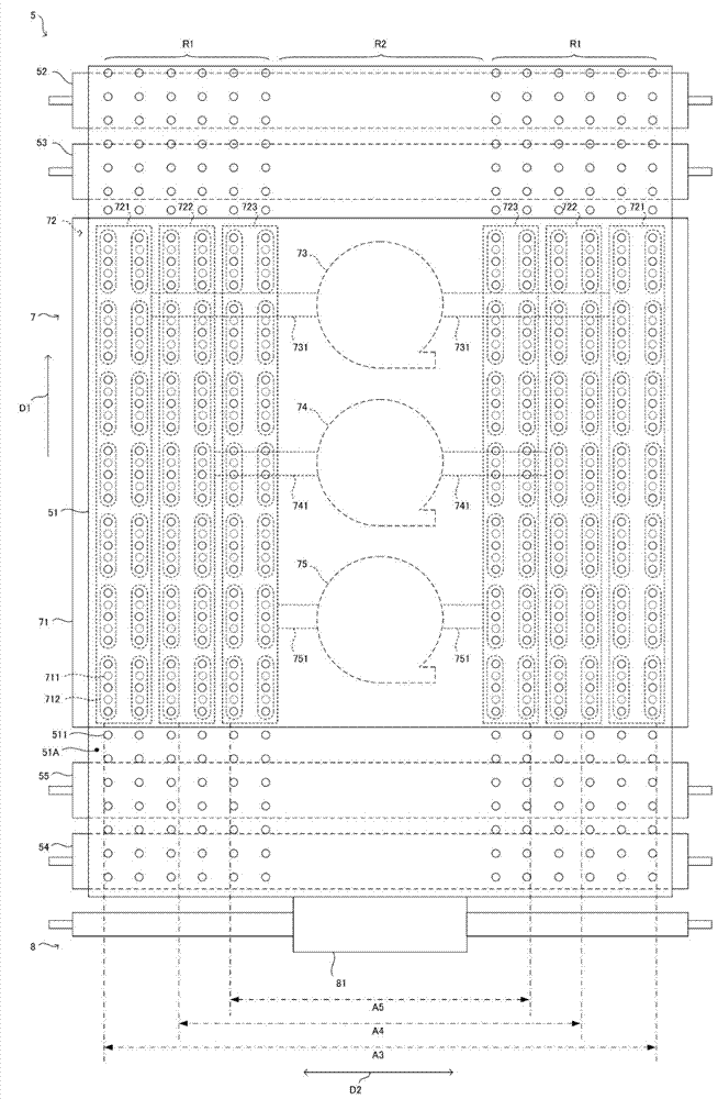
[0126] Next, a second embodiment of the present invention will be described. In addition, in this second embodiment, the description of the same configuration and processing as those of the first embodiment will be omitted, and the points of difference from the first embodiment will be described. here, Figure 6 A schematic view of the conveyor belt 51 viewed from above, Figure 7 It is a diagram showing the circuit configuration of the charging unit 8 .

[0127] Such as Figure 6As shown, in the width direction D2 perpendicular to the conveying direction D1 of the sheet P and in the predetermined plurality of suction and adsorption areas R1 corresponding to the ends of various sizes of the sheet P Inside, the tape openings 511 are formed at predetermined intervals in the conveyance direction D1. More specifically, each of the belt openings 511 is formed such that an end surface of the sheet P in the width direction D2 corresponding to the size of the sheet P corresponding...


PUM


Abstract

A sheet conveying device includes a conveyance belt, a conveyance plate, an air intake portion, and a charging portion. The conveyance belt has a plurality of belt openings formed in a previously-set suction attraction region in end portions thereof in a width direction perpendicular to a conveyance direction of a sheet, and conveys the sheet. The conveyance plate has a plurality of platen openings formed therein at positions corresponding to the belt openings in the width direction, and is disposed on a back surface side of the conveyance belt. The air intake portion suctions air through the belt openings and the platen openings from the back surface side of the conveyance plate. The charging portion charges a previously-set electrostatic attraction region in a center portion in the width direction of the conveyance belt.

Description

technical field [0001] The present invention relates to a sheet conveying device and an image forming apparatus that make a sheet adsorb and convey on a conveying belt by suction adsorption and electrostatic adsorption. Background technique [0002] In general, an inkjet recording device (an example of an image forming device) that records an image by ejecting ink from a recording head onto a sheet is well known. Also, there is a so-called line head type inkjet recording apparatus that includes recording heads for each color arranged along a sheet conveyance path as types of inkjet recording apparatuses. This type of inkjet recording device is equipped with a sheet conveying device that conveys the sheet in a state facing the ink ejection surface of each recording head by a conveying belt, and ink is ejected from each recording head onto the sheet being conveyed. . [0003] In addition, the sheet is electrostatically adsorbed on the conveyor belt by forming an alternating ...

Claims


Application Information

Patent Timeline
Patent Type & Authority Applications(China)
IPC IPC(8): B65H5/22B65H5/02
CPCB65H3/128B65H3/18B41J29/377B65H7/20B65H5/004B65H5/021B65H5/224B65H7/02B65H2406/362B65H2406/3662B65H2511/12B65H2515/805B65H2801/15B41J11/0085B41J11/007B65H2515/34B65H2220/01B65H2220/02B41J13/08B41J15/048B41J13/226
Inventor 上田博之
Owner KYOCERA DOCUMENT SOLUTIONS INC
Why Eureka
Try Eureka