Method and device for monitoring the production of a knitting machine

A knitting machine and knitting path technology, applied in weft knitting, textile and paper making, knitting, etc., can solve problems such as complex time expectations

Active Publication Date: 2015-04-15
MEMMINGER IRO GMBH
View PDF11 Cites 8 Cited by
  • Summary
  • Abstract
  • Description
  • Claims
  • Application Information

AI Technical Summary

Problems solved by technology

Specifically, determining the time between two pulses and the expected value depending on the pumping speed is complicated in each case

Method used


Image

  • Method and device for monitoring the production of a knitting machine
  • Method and device for monitoring the production of a knitting machine
  • Method and device for monitoring the production of a knitting machine

Examples


Embodiment Construction

[0120] first example

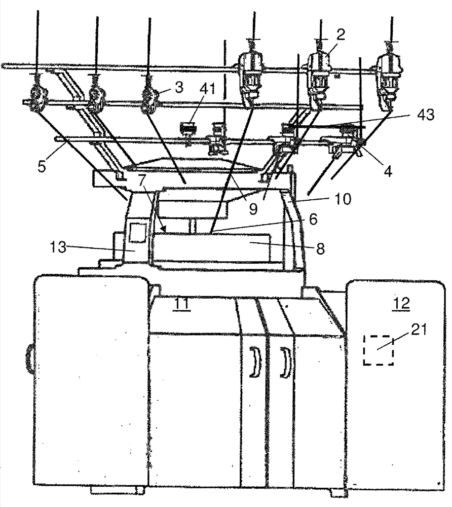
[0121] figure 1 A circular knitting machine 1 with elements of a device according to the invention for monitoring the production of the knitting machine, hereinafter referred to as monitoring device, is shown by means of a schematic diagram.

[0122] The circular knitting machine 1 has a plurality of thread supply devices, and in particular a thread supply device configured as a storage thread supply device 1 , a tension control thread supply device 3 and an active thread supply device 4 .

[0123] The thread feeding devices are arranged on a plurality of carrier rings 5 ​​of the circular knitting machine 1 . exist figure 1 In , only some of the wire feeding devices are shown, of which three storage wire feeding devices 2 can be seen on the upper carrier ring 5, three wire tension controlled wire feeding devices 3 can be seen on the central carrier ring 5, and Three positive wire feeding devices 4 can be seen on the lower body ring 5 .

[0124] The c...


PUM


Abstract

The invention relates to a method and device for monitoring the production of a knitting machine, and the knitting machine; the method for monitoring the production of a knitting machine is provided; wire supply of at least one wire supply device is monitored by a sensor device (19) and a control unit (20); a sensor signal (S) with a measuring pulse (I) for each length unit (delta XF) of a wire supply path is generated by the sensor device (19) in such condition. The sensor signal (S) is evaluated by the control unit (20); in a suitable condition, the control unit (20) is used for generating a stop signal (ST) for the knitting machine; a clock signal (S2) aiming at the control unit (20) is provided by a clock unit; a clock pulse (T) of the clock signal (S2) is matched with the length unit (delta XS) of a knitting path; the length unit (delta XS) of the knitting path is one/Zth of the length unit (delta XF) of the wire supply path (wherein the factor Z is at least 2, preferably 3-10); the sensor signal (S) is evaluated by the control unit (20), and depends on the generation of the clock signal (S2).

Description

technical field [0001] The invention relates to a method and a device for monitoring the production of a knitting machine. Background technique [0002] In weaving technology it is often desirable to monitor current production. For this purpose it is known from EP 0 752 631 B1 to monitor the feed of a large number of threads into a textile machine. Sensor means are provided which detect the state of the wire feeding into the machine, in particular the movement or stopping of the wire, the tension and the speed. The sensor devices are connected to a control unit which controls the operation of the machine based on the sensor signals. The control unit is connected to the sensor device by means of at least one communication conductor. [0003] The control unit independently interrogates the sensor means on the basis of a periodic reference signal, which varies with the operating state of the textile machine, relating to data about the state of the supply of thread. The cont...

Claims


Application Information

Patent Timeline
Patent Type & Authority Applications(China)
IPC IPC(8): D04B35/10D04B35/14D04B15/38
CPCD04B35/14D04B35/12D04B15/48D04B15/484
Inventor M.克歇尔F.奥内达
Owner MEMMINGER IRO GMBH
Why Eureka
Try Eureka