Solar warning lamp

A warning light and solar energy technology, applied in the field of warning lights, can solve problems such as inconvenient use, manual management of warning lights, and easy water ingress

Inactive Publication Date: 2015-04-15
TONGMING OPTOELECTRONICS TECH
View PDF5 Cites 4 Cited by
  • Summary
  • Abstract
  • Description
  • Claims
  • Application Information

AI Technical Summary

Problems solved by technology

[0003] Existing solar warning lights include a solar receiving panel, a rechargeable battery, a light-emitting diode, a control circuit board and a casing. The casing includes a transparent cover and a base. The rechargeable battery is built into the base. , the solar receiving board is fixed on the upper cover of the shell and connected to the control circuit board. The warning light with the above structure has the following disadvantages: the warning light adopts a lampshade with a single reflective surface, which does not have obvious buffering and refracting effects on the light source. Therefore, the light source is concentrated In the center of the reflective surface of the warning light lampshade, the brightness of the reflective surface is not uniform, and the irradiation distance is not far enough, and the warning light needs manual management, and cannot be turned on and off automatically, which is very inconvenient to use
The power switch generally adopts a toggle switch, which is installed on the shell of the warning light. The waterproof performance is poor, and it is easy to enter water, causing switch failure.

Method used


Image

  • Solar warning lamp
  • Solar warning lamp

Examples


Embodiment Construction

[0012] The implementation of the present invention is as follows:

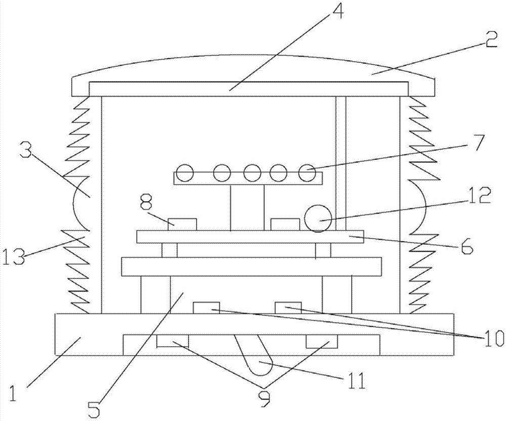
[0013] like figure 1 As shown, the solar warning light of the present invention includes a lamp holder 1, a lamp cover 2 and a lampshade 3, the lamp cover 2 is provided with a solar receiving plate 4, and the lamp holder 1 is provided with a rechargeable battery connected to the solar receiving plate 4. Lithium battery 5, control circuit board 6 and light-emitting diode 7, the outside of described control circuit board 4 is provided with photosensitive switch 8, and described lamp holder 1 is provided with manual switch 11, and manual switch consists of two magnets 9 and corresponding Two dry reed switches 10 are formed, and the dry reed switches are connected with the control circuit board. An infrared receiver 12 is arranged on the outside of the control circuit board.

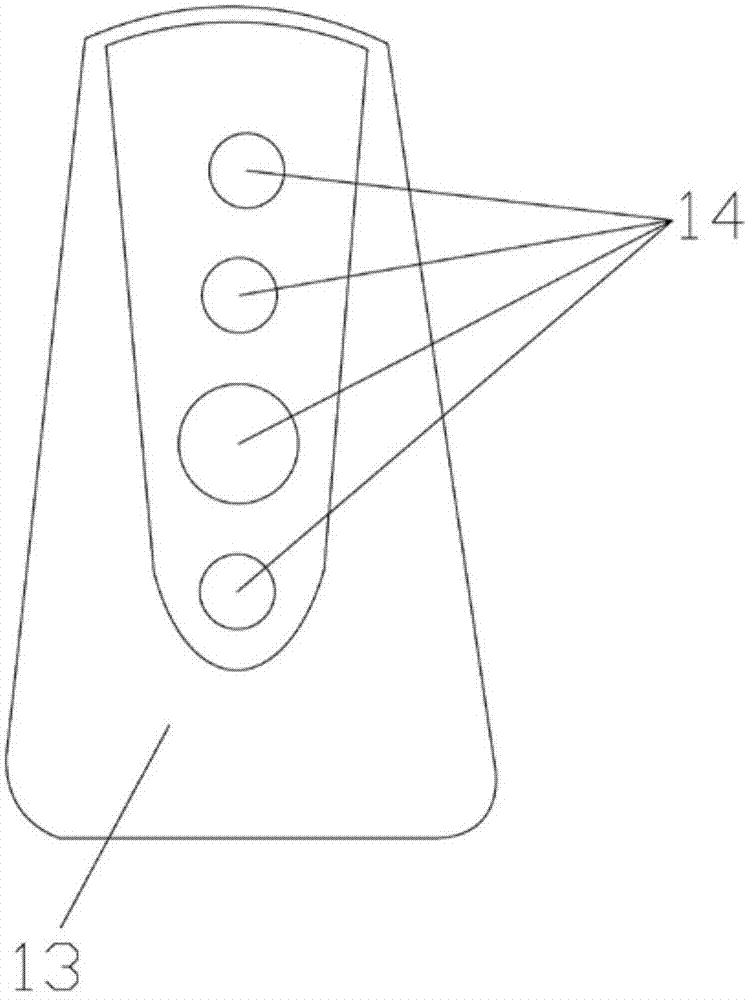
[0014] The lampshade 3 is designed as a 360° vertical concave lens on the inner surface, and the outer surface is composed of thirteen ho...


PUM


Abstract

The invention provides a solar warning lamp having the characteristics of high brightness, automatic opening and closing, capability of being on and off through remote control by an infrared remote controller and capability of selecting a flicker mode. The solar warning lamp comprises a lamp base, a lamp cover and a lamp housing, wherein a solar panel is arranged on the lamp cover; and the lamp base is provided with a high-energy rechargeable lithium battery, a control circuit board and a light emitting diode connected with the solar panel. A photosensitive switch is arranged on the control circuit board, is automatically closed in the daytime, and is automatically opened at night. A manual switch consisting of a magnet and a reed switch is arranged on the base, and has three gears. The middle gear is a main switch; the right gear is an automatic gear, is closed in the daytime, and is opened at night; and the left gear is located in a working mode in the daytime and at night, and the LED emits light. In addition, an integrated circuit on an electronic control board can be programmed, can be set with multiple flicker modes, and can be remotely controlled through the remote controller. Inner and outer reflecting surfaces are arranged on the lamp housing; vertical strip concave lenses are arranged at the whole periphery of the inner surface; and thirteen layers of convex lenses are transversely arranged on the outer surface. The light emitted by the LED is more uniform through the refraction of the concave lenses and the convex lenses; and the irradiation distance of the warning lamp is largely increased.

Description

technical field [0001] The invention relates to a warning light, in particular to a solar warning light. Background technique [0002] In airports, wharves, high-rise buildings and other occasions, warning lights of different colors need to be installed. These lights are placed on the highest points of buildings or installed on rivers, lakes and seas. It is usually very inconvenient to supply power, so solar warning lights have been widely used. [0003] Existing solar warning lights include a solar receiving panel, a rechargeable battery, a light-emitting diode, a control circuit board and a casing. The casing includes a transparent cover and a base. The rechargeable battery is built into the base. , the solar receiving board is fixed on the upper cover of the shell and connected to the control circuit board. The warning light with the above structure has the following disadvantages: the warning light adopts a lampshade with a single reflective surface, which does not have ...

Claims


Application Information

Patent Timeline
Patent Type & Authority Applications(China)
IPC IPC(8): F21S9/03F21S10/06F21V23/04
CPCF21S9/037F21S10/066F21V23/003F21V23/0435F21Y2101/00F21Y2103/10F21Y2111/00F21Y2115/10
Inventor 饶国才
Owner TONGMING OPTOELECTRONICS TECH
Why Eureka
Try Eureka