
FPGA-based infrared focal plane array blind pixel detection system and FPGA-based infrared focal plane array blind pixel detection method

An infrared focal plane and blind element technology, which is applied to electrical radiation detectors and other directions, can solve the problems of low blind element detection efficiency, affect image quality, and unfavorable observation, so as to ensure detection efficiency and real-time performance, and blind element collection is comprehensive and accurate. , the effect of improving the detection accuracy

Inactive Publication Date: 2015-04-15
NANJING UNIV OF SCI & TECH
View PDF4 Cites 15 Cited by
  • Summary
  • Abstract
  • Description
  • Claims
  • Application Information

AI Technical Summary

Problems solved by technology

When the number of blind pixels is too large or clustered, it will seriously affect the image quality, which is very unfavorable for observation
[0003] Blind element detection techniques widely used in infrared imaging systems include calibration method, linear extrapolation failure element detection method and 3σ detection method, all of which determine whether the specified pixel is a blind element according to certain criteria: calibration The blind element detection method is based on the response of the infrared focal plane array to the high-temperature heat source and the low-temperature heat source; the linear extrapolation invalid element detection method is used to detect the blind element based on the gray gradient changes of the upper and lower, left and right, or diagonal lines in a window. ; The 3σ detection method is based on the premise that the response value of the infrared focal plane array pixel obeys the normal distribution, and the blind element is detected according to the 3σ rule in probability. However, this method does not fully consider different temperature conditions. New blind cells may appear when the focal plane enters too high or too low temperature
To sum up, the current methods can perform effective blind element detection, but there are still many missed judgments that cannot be ignored, and there are shortcomings of low efficiency, poor quality, and difficult implementation of blind element detection.

Method used


Image

  • FPGA-based infrared focal plane array blind pixel detection system and FPGA-based infrared focal plane array blind pixel detection method
  • FPGA-based infrared focal plane array blind pixel detection system and FPGA-based infrared focal plane array blind pixel detection method
  • FPGA-based infrared focal plane array blind pixel detection system and FPGA-based infrared focal plane array blind pixel detection method

Examples


Embodiment 1

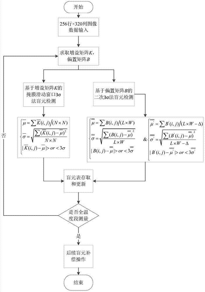
[0042] Assuming that the size of the image accessed by the infrared focal plane array is 256 rows × 320 columns, the specific steps of the FPGA-based infrared focal plane array blind element detection method are as follows:

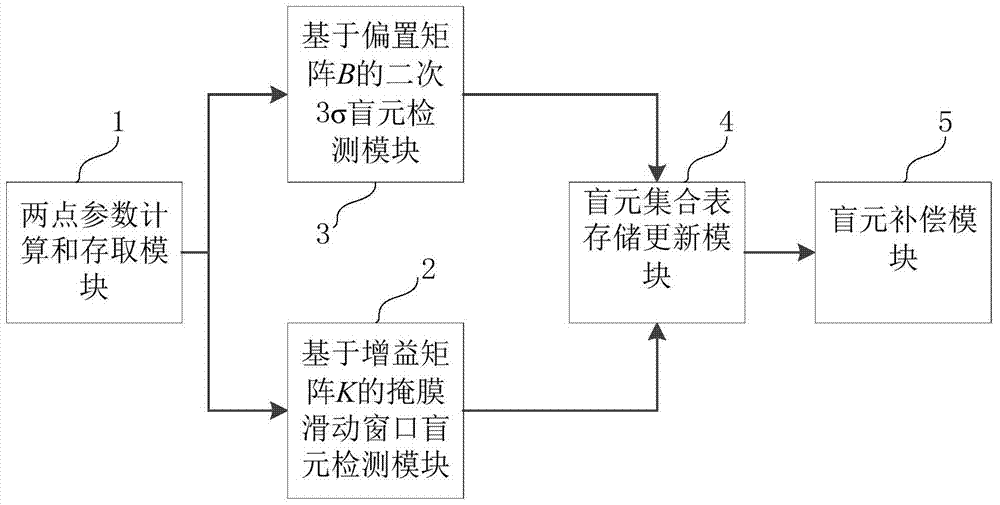
[0043] Step 1, two-point parameter calculation and access: the infrared imaging system performs N=50 two-point corrections on the 10°C surface source blackbody, and obtains 50 sets of two-point parameter matrices, and then calculates the average value respectively to obtain the average gain matrix K , the size of the bias matrix B, matrix K and B is 256 rows × 320 columns, and the gain matrix K and bias matrix B are stored in the internal RAM of the FPGA for use by subsequent modules.

[0044] Step 2, the mask sliding window blind element detection module 2 based on the gain matrix K reads the gain matrix K in the two-point parameter matrix stored in the internal RAM, and uses the mask sliding window 3σ rule to perform blind element detection to obtain the...


PUM


Abstract

The invention discloses an FPGA-based infrared focal plane array blind pixel detection system and an FPGA-based infrared focal plane array blind pixel detection method. The system comprises a two-point parameter calculation and storage module, a mask slide window blind pixel detection module based on a gain matrix K, a secondary 3Sigma blind pixel detection module based on a bias matrix B, a blind pixel set table storage and update module, and a blind pixel compensation module. The detection method comprises the following steps: performing two-point parameter calculation on an original digital image signal to obtain a two-point parameter matrix and storing the two-point parameter matrix in an internal RAM of an FPGA; carrying out mask slide window blind pixel detection based on the gain matrix K and secondary 3Sigma blind pixel detection based on the bias matrix B on the two-point parameter matrix and combining the results of two times of blind pixel detection to obtain a blind pixel set table; and adjusting the detection temperature and repeating the above steps to obtain blind pixel set tables corresponding to different temperatures, and sorting and merging the blind pixel set tables corresponding to different temperatures for subsequent compensation. The system and the method of the invention have the advantages of high detection efficiency and good quality, and missing pixels can be reduced in detection.

Description

technical field [0001] The invention belongs to the technical field of infrared image enhancement, in particular to an FPGA-based infrared focal plane array blind element detection system and method. Background technique [0002] In the infrared focal plane imaging system, the number of blind elements is a very important evaluation index, which directly determines the quality of the infrared focal plane. When the number of blind pixels is too large or clustered, the image quality will be seriously affected, which is very unfavorable for observation. [0003] Blind element detection techniques widely used in infrared imaging systems include calibration method, linear extrapolation failure element detection method and 3σ detection method, all of which determine whether the specified pixel is a blind element according to certain criteria: calibration The blind element detection method is based on the response of the infrared focal plane array to the high-temperature heat sourc...

Claims


Application Information

Patent Timeline
IPC IPC(8): G01J5/10
Inventor 顾国华张桥舟陈钱隋修宝钱惟贤路东明何伟基于雪莲
Owner NANJING UNIV OF SCI & TECH
Learn More