Underwater photoelectric separating cabin

A technology of photoelectric separation and photoelectric composite cable, applied in the direction of cable joints, etc., can solve the problems of sealing reliability and structural strength contradiction, and achieve the effect of facilitating construction adjustment, light weight and small volume

Active Publication Date: 2015-04-15
SHENYANG INST OF AUTOMATION - CHINESE ACAD OF SCI
View PDF6 Cites 4 Cited by
  • Summary
  • Abstract
  • Description
  • Claims
  • Application Information

AI Technical Summary

Problems solved by technology

[0005] In order to solve the problem of conflicting sealing reliability and structural strength of the sealed cabin body as a structural load-bearing component, the object of the present invention is to provide an underwater photoelectric separation cabin

Method used


Image

  • Underwater photoelectric separating cabin
  • Underwater photoelectric separating cabin
  • Underwater photoelectric separating cabin

Examples


Embodiment Construction

[0019] The present invention will be described in further detail below in conjunction with the accompanying drawings.

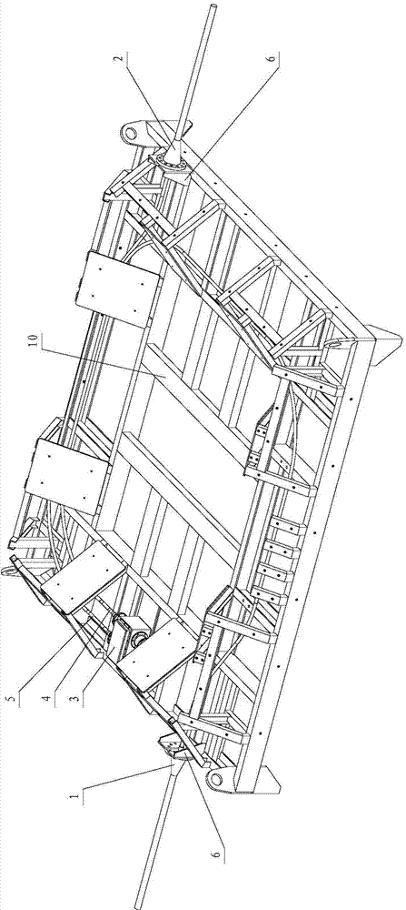
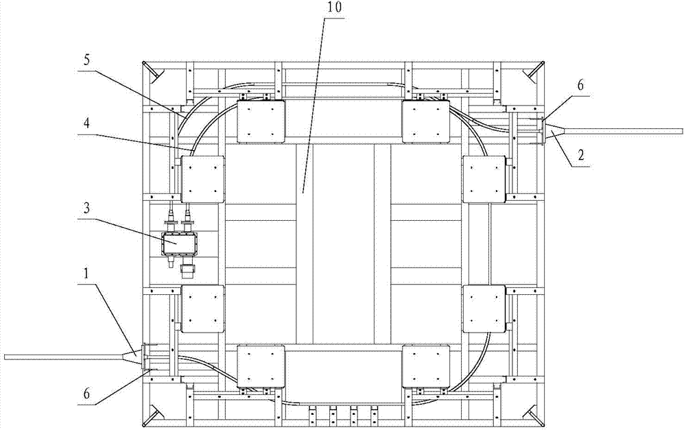
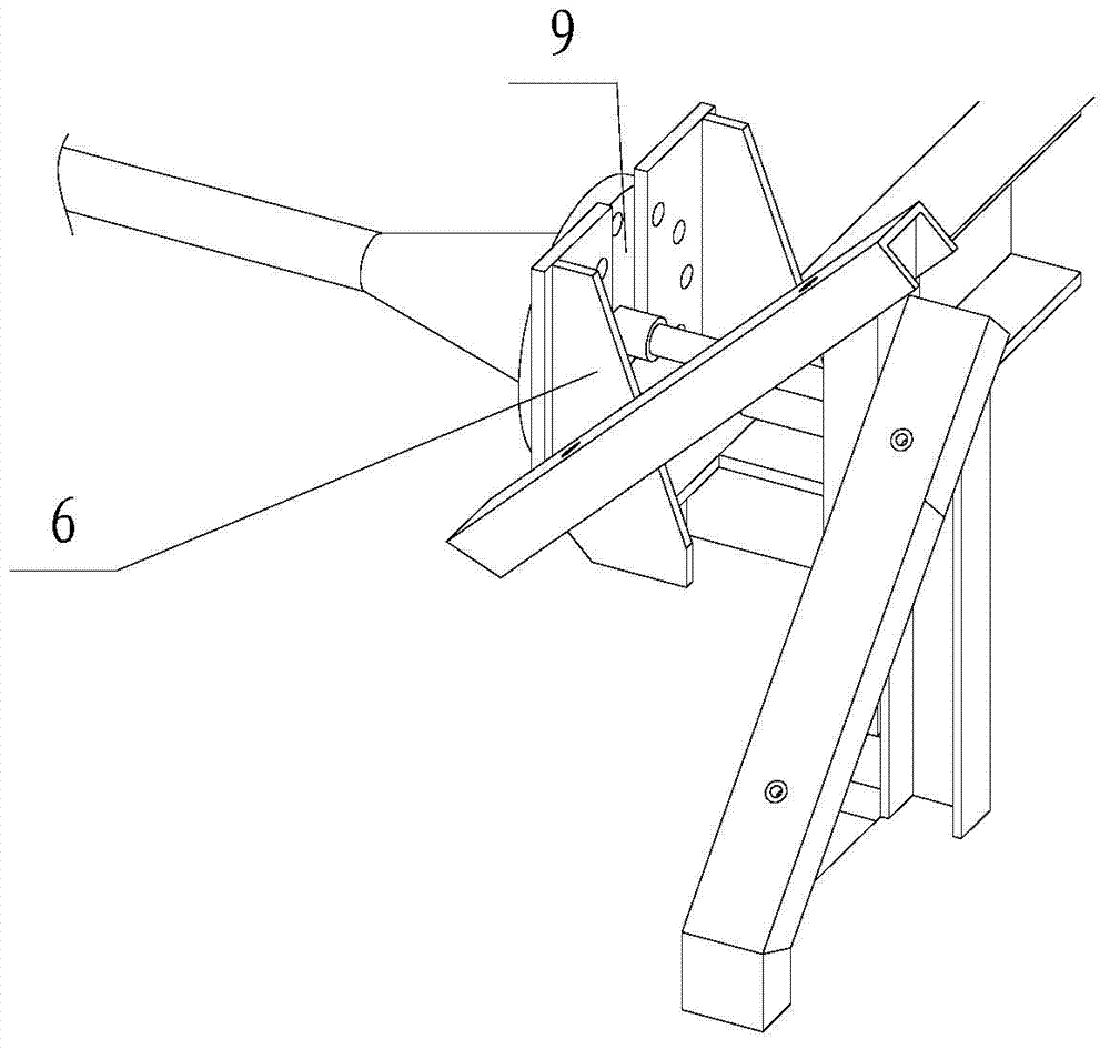
[0020] Such as figure 1 , figure 2 As shown, the present invention includes a structural frame 10, a submarine cable load-bearing end and a photoelectric separation cabin 3, wherein the submarine cable load-bearing end is installed on the structural frame 10, and a flange 6 is fixed on the structural frame 10, and a flange 6 is fixed on the flange 6. A U-shaped opening is provided to facilitate the disassembly and maintenance of the submarine cable. The load-bearing end of the submarine cable is provided with a butt flange 9, and the steel wire armored sheath of the outer layer of the submarine cable is pressed against the butt flange 9, and the butt flange 9 is fixed to the U-shaped opening of the flange 6 by bolts. The number of the load-bearing end of the submarine cable is the same as that of the flange 6, which is one or more; two flanges 6 are fixed ...


PUM


Abstract

The invention relates to submarine observation network equipment, and particularly relates to an underwater photoelectric separating cabin comprising a structural framework, submarine cable force-bearing end heads and a photoelectric separating cabin. The submarine cable force-bearing end heads are installed on the structural framework. Force borne by a submarine cable is borne by the structural framework. Photoelectric composite cables of which steel wire armored sheaths are removed are coiled in the structural framework. The photoelectric separating cabin is installed in the structural framework. The photoelectric composite cables enter into the photoelectric separating cabin via through-wall sealing components, and photoelectric separation is completed via the photoelectric separating cabin. A separated optical channel and an electric channel are led out to lower level equipment to work by the photoelectric separating cabin through the through-wall sealing components. Force borne by the submarine cable is borne by the structural framework so that the underwater photoelectric separating cabin is suitable for the requirements of special equipment, small in size, low in weight, economical in installing space and more suitable for the complex wiring requirements of narrow space.

Description

technical field [0001] The invention relates to seabed observation network equipment, in particular to an underwater photoelectric separation cabin. Background technique [0002] On the main node of the submarine observation network, power supply and communication need to be carried out through the photoelectric composite cable on the seabed. use. [0003] In order to prevent the dragging of fishing nets and the destruction of marine organisms, the submarine photoelectric composite cable generally has a strong steel wire armored sheath with high tensile strength, which also leads to a large bending radius, which makes it difficult to arrange in a small space. [0004] In order to ensure reliable fixation of the submarine cable, a strong fixing platform is required. If the photoelectric separation cabin is combined with the fixed platform, the structural strength requirements for the photoelectric separation cabin will be greatly increased, and the sealed cabin body will be...

Claims


Application Information

Patent Timeline
Patent Type & Authority Applications(China)
IPC IPC(8): H02G15/10
CPCH02G15/10
Inventor 何震李智刚孙凯任福琳梁洪光李默竹
Owner SHENYANG INST OF AUTOMATION - CHINESE ACAD OF SCI
Why Eureka
Try Eureka