Method for producing Li-ion battery module and corresponding Li-ion battery module

A technology of lithium-ion batteries and battery modules, which is applied in the direction of large-size batteries/battery packs, small-size batteries/battery packs, and isolation of batteries from their environment, and can solve problems such as different battery densities

Inactive Publication Date: 2015-04-15
ROBERT BOSCH GMBH
View PDF4 Cites 12 Cited by
  • Summary
  • Abstract
  • Description
  • Claims
  • Application Information

AI Technical Summary

Problems solved by technology

Also, find a solution that is tolerant to fluctuations in the manufacturing process that can lead to different cell densities

Method used


Image

  • Method for producing Li-ion battery module and corresponding Li-ion battery module
  • Method for producing Li-ion battery module and corresponding Li-ion battery module
  • Method for producing Li-ion battery module and corresponding Li-ion battery module

Examples


Embodiment Construction

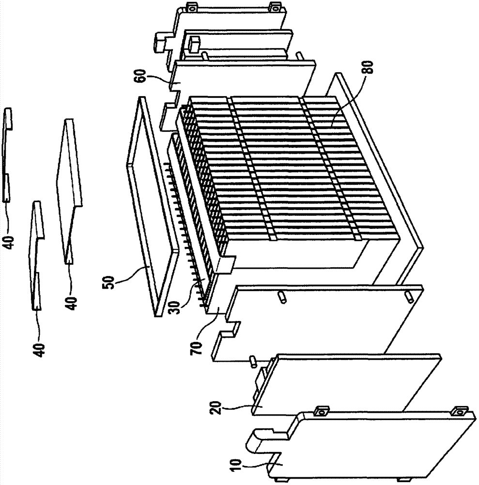
[0025] image 3 A schematic diagram of an exemplary arrangement for constructing a mechanically pressed battery is shown.

[0026] exist image 3 Among them, reference numeral 10 denotes the cover plate of the electronic device, 20 denotes the control electronics, 30 denotes the laser-welded connection rail, 40 denotes the connection cover, 50 denotes the pressure strap, 60 denotes the pressure plate, 70 denotes the prismatic lithium-ion battery And reference numeral 80 designates a cooling body.

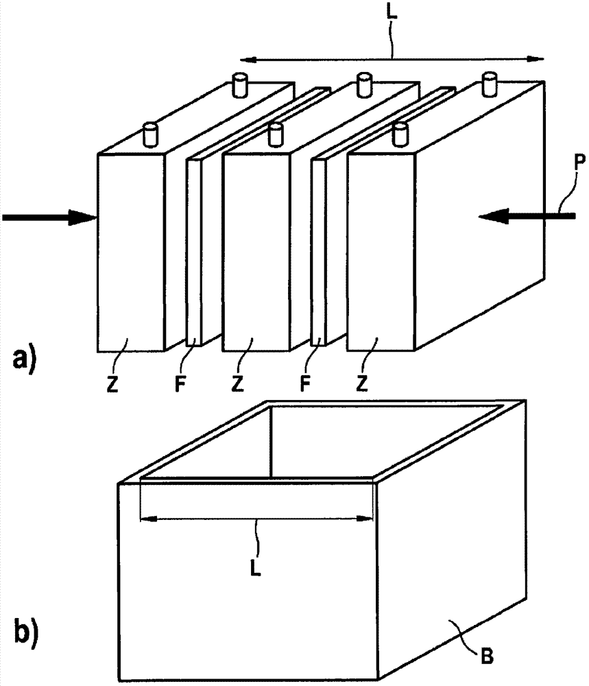
[0027] figure 1 a is a schematic view of a lithium-ion battery module produced according to an embodiment of the method according to the invention and figure 1 b is a schematic illustration of the housing of a lithium-ion battery module produced according to one embodiment of the method according to the invention.

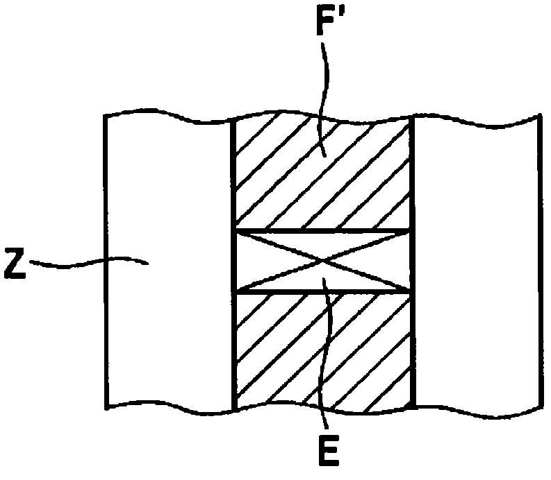
[0028] exist figure 1 In a) and b), reference sign Z denotes a battery of the battery module. The reference F designates the elastic-plastic membrane and L the lo...


PUM


Abstract

A method for manufacturing lithium-ion battery modules, including the following: positioning an elastic plastic device between at least two cells of a battery module; path-controlled compression of the at least two cells of the battery module and of the elastic plastic device situated between the at least two cells. Also described is a corresponding lithium-ion battery module.

Description

technical field [0001] The invention relates to a method for producing a lithium-ion battery module and a corresponding lithium-ion battery module. Background technique [0002] image 3 A schematic diagram of an exemplary arrangement for constructing a mechanically pressed battery is shown. [0003] exist image 3 Among them, reference numeral 10 denotes the cover plate of the electronic device, 20 denotes the control electronics, 30 denotes the laser-welded connection rail, 40 denotes the connection cover, 50 denotes the pressure strap, 60 denotes the pressure plate, 70 denotes the prismatic lithium-ion battery And reference numeral 80 designates a cooling body. [0004] It is known that the mechanical stresses acting on lithium-ion batteries have a positive influence on their service life under certain circumstances. [0005] In addition, mechanical compression is often used for mechanical fixation. Batteries are also often pressed for thermal contact to cool the batte...

Claims


Application Information

Patent Timeline
Patent Type & Authority Applications(China)
IPC IPC(8): H01M2/02H01M2/10H01M2/34H01M10/0525H01M50/209H01M50/213H01M50/291H01M50/293
CPCY02E60/122H01M10/0404H01M10/0525H01M2/1061H01M2/345H01M2/105H01M2/0245H01M50/258H01M50/209H01M50/213H01M50/578H01M50/291H01M50/293Y10T29/49108H01M10/0481Y02E60/10Y02P70/50H01M10/058H01M10/6555H01M10/653H01M50/20H01M50/10H01M50/572H01M50/24
Inventor N·多奇
Owner ROBERT BOSCH GMBH
Why Eureka
Try Eureka