Electrofusion forming method for evaporator cylinder in nuclear power plant

A technology for evaporators and nuclear power plants, applied in welding equipment, metal processing equipment, manufacturing tools, etc., can solve the problems of affecting the mechanical properties of materials, complex processes, difficult control of chemical and mechanical properties, etc., and achieve outstanding corrosion resistance and other properties. The effect of simplifying the processing process and shortening the product cycle

Active Publication Date: 2016-08-17
NANFANG ADDITIVE MFG TECH
View PDF5 Cites 0 Cited by
  • Summary
  • Abstract
  • Description
  • Claims
  • Application Information

AI Technical Summary

Problems solved by technology

This method is widely used in production and can also meet the quality requirements, but for the gradually increasing demand for material components, forging, especially heat treatment, is prone to problems such as very uneven macroscopic material phase structure. The process is complex, chemical and It is difficult to control the mechanical properties, which also leads to poor quality stability and high scrap rate
At the same time, judging from the final grain measurement results of this process, it is generally only about 5-7 grades. For the purpose of improving the mechanical properties, especially the comprehensive performance of strength and toughness, by further refining the grains in the current research and development and production, this Process has a big bottleneck
[0005] In addition, the method of segmented material forging and tailor welding used in the evaporator equipment also severely splits the continuous direction of the mechanical fibers due to the increase in the weld seam, which greatly affects the mechanical properties of the material and the safety of the container equipment. And it is also very easy to cause the delay of the manufacturing period and increase the cost.

Method used


Image

  • Electrofusion forming method for evaporator cylinder in nuclear power plant
  • Electrofusion forming method for evaporator cylinder in nuclear power plant
  • Electrofusion forming method for evaporator cylinder in nuclear power plant

Examples


Embodiment Construction

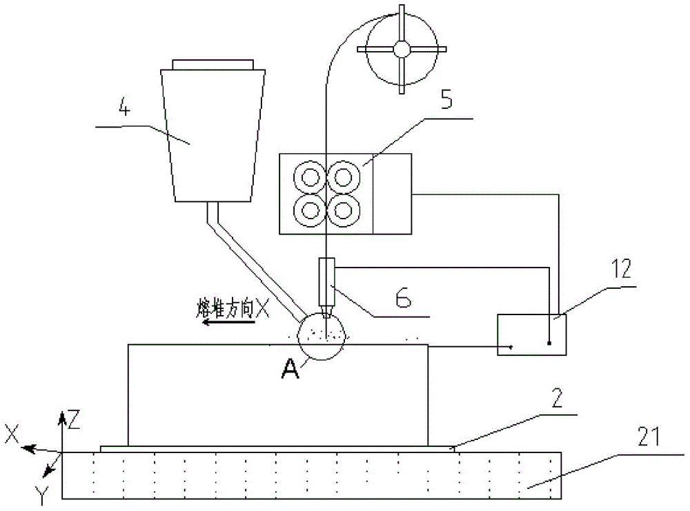
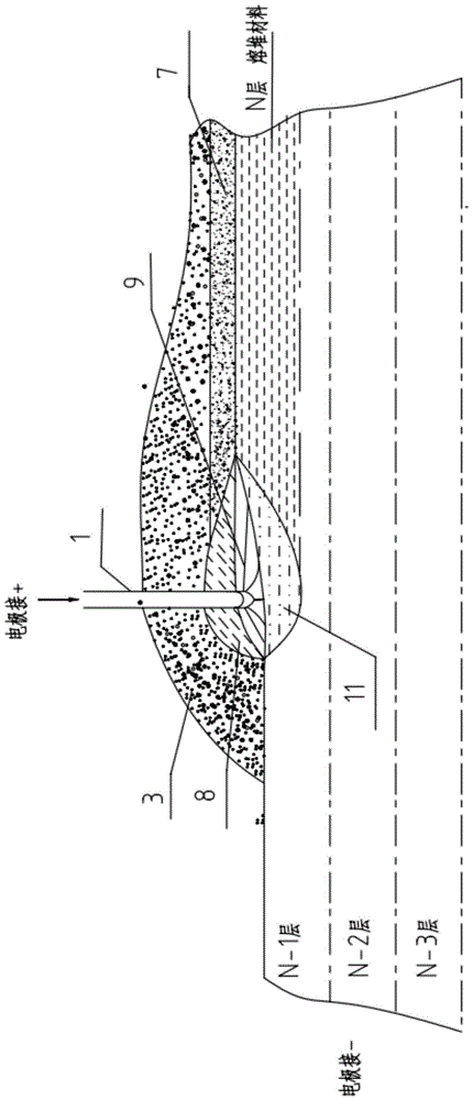
[0021] Specific embodiments of the present invention will be described below with reference to the accompanying drawings. Figure 1A It is a schematic diagram for illustrating the electrofusion forming method in the specific embodiment; Figure 1B for Figure 1A Partial enlarged view near the location shown in A. Since it is a schematic diagram, the components in the diagram are schematic, and their actual shapes and dimensions are not limited by the diagram.

[0022] In this forming method, the raw wire material 1 is melted and deposited layer by layer (shown in FIG. 1 as the state when the Nth layer is deposited) on the base material 2, thereby finally forming a desired metal member.

[0023] The specific implementation process is:

[0024] A. The wire feeding mechanism 5 sends the raw material wire 1 to the surface of the base material 2 placed on the workbench 21 , which is covered with the granular auxiliary materials conveyed by the powder feeding mechanism 4 .

[0025...


PUM

PropertyMeasurementUnit
diameteraaaaaaaaaa
surface temperatureaaaaaaaaaa
thicknessaaaaaaaaaa

Abstract

An electric melting method for forming a nuclear power plant evaporator cylinder: an electric melting head (6) and a substrate (2) respectively are connected to either electrode of a power source (12), when forming, a raw material wire (1) is fed to a surface of the substrate (2) via a wire feeder mechanism (5) and the electric melting head (6), under the protection of a stack of a granular auxiliary material (3), the raw material wire (1) is molten under the effects of three heat sources, namely electric arc heat, resistance heat, and electroslag heat, a partly molten pool (11) is formed on the surface of the substrate (2), conveyance of the raw material wire (1) and the auxiliary material (3) is continued, a computer is employed to control relative movements of the electric melting head (6) and of the substrate (2) on the basis of layer slicing data of a forming component, rapid cooling and layer-by-layer solidification and deposition of the molten pool (11) on the substrate is implemented, and finally, the nuclear power plant evaporator cylinder is formed. The method is highly efficient and inexpensive. The nuclear power plant evaporator cylinder formed is provided with great mechanical properties.

Description

technical field [0001] The invention relates to an electromelting forming method for an evaporator cylinder body of a nuclear power plant. Background technique [0002] The steam generator is one of the core equipment in the primary circuit system of a nuclear power plant. It is the key component for the cooling water of the secondary circuit to be evaporated into steam after heat exchange with the high-pressure water of the primary circuit to drive the steam turbine to do work to realize power generation. It is also the hub of heat conversion between the primary and secondary circuits. In the nuclear power primary circuit system, the evaporator equipment is the heaviest (the total weight of a typical AP1000 vessel is 600 tons), and the largest size (the diameter of the upper vessel section of the AP1000 is more than 5 meters, and the total height of the vessel is more than 20 meters), plus the harsh working environment and The increasingly extreme safety requirements, so th...

Claims


Application Information

Patent Timeline
Patent Type & Authority Patents(China)
IPC IPC(8): B23K28/02
CPCB23K28/02
Inventor 不公告发明人
Owner NANFANG ADDITIVE MFG TECH
Why Eureka
Try Eureka