Drag chain device and cutting device

A drag chain device, cutting device technology, applied in the direction of auxiliary devices, welding/cutting auxiliary equipment, gas flame welding equipment, etc., can solve the problem that the cutting torch cannot be rotated

Inactive Publication Date: 2015-04-22
上海气焊机厂有限公司
View PDF11 Cites 4 Cited by
  • Summary
  • Abstract
  • Description
  • Claims
  • Application Information

AI Technical Summary

Problems solved by technology

[0004] However, the drag chain device of the above-mentioned cutting device moves in a straight l

Method used


Image

  • Drag chain device and cutting device
  • Drag chain device and cutting device
  • Drag chain device and cutting device

Examples


Embodiment Construction

[0035] In order to facilitate the understanding of the present invention, the present invention will be described more fully below with reference to the associated drawings. Preferred embodiments of the invention are shown in the accompanying drawings. However, the present invention can be embodied in many different forms and is not limited to the embodiments described herein. On the contrary, these embodiments are provided to make the understanding of the disclosure of the present invention more thorough and comprehensive.

[0036] It should be noted that when an element is referred to as being “fixed” to another element, it can be directly on the other element or there can also be an intervening element. When an element is referred to as being "connected to" another element, it can be directly connected to the other element or intervening elements may also be present. In contrast, when an element is referred to as being "directly on" another element, there are no interveni...


PUM


Abstract

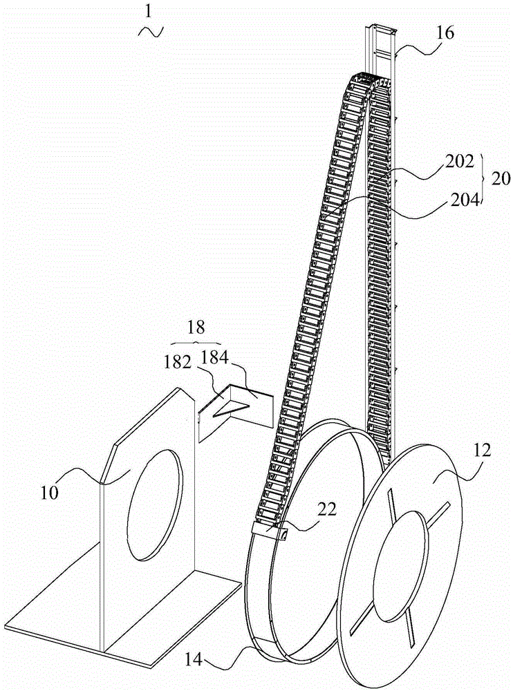
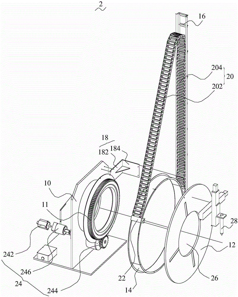
A drag chain device comprises a fixed base, a rotary disc, a guiding ring, a guiding groove and a drag chain. The rotary disc is in rotating connection with the fixed base. The guiding ring is connected with the rotary disc and arranged along the edge of the rotary disc. The guiding groove is formed in the side edge of the guiding ring, and the guiding groove and the guiding ring are located on the same plane. The guiding groove is connected with the fixed base through an installation base. One end of the drag chain is connected with the rotary disc, and the other end of the drag chain is connected with the guiding groove. A cable is fixed on the drag chain device. When the rotary disc rotates, the drag chain is wound around the guiding ring along with rotation of the rotary disc under the action of the guiding groove and the guiding ring, then the cable is wound around the guiding ring along with the drag chain, and the cable can circularly move along with a moving body. According to a cutting device using the drag chain device, a cutting torch can rotate around a profiled bar, and it is ensured that cutting is carried out smoothly.

Description

technical field [0001] The invention relates to the field of steel material cutting, in particular to a drag chain device and a cutting device. Background technique [0002] In the process of steel processing, the cutting of profiled materials is often involved. Profiles, that is, metal profiles other than the commonly used profiles published by national standards, generally rectangular tubes and H-shaped steel. [0003] Generally, the cutting of the profile is to cut the torch around the profile with the cable connected. In order to avoid the mess of the cable, the cable of the torch is usually fixed on the drag chain device. Moves with the movement of the torch, so that the cable line of the torch is more tidy. [0004] However, the drag chain device of the above-mentioned cutting device moves linearly with the moving body, which cannot realize the rotation of the cutting torch along the periphery of the profiled bar. Contents of the invention [0005] Based on this, ...

Claims


Application Information

Patent Timeline
IPC IPC(8): B23K37/00
CPCB23K7/10B23K7/00B23K37/00
Inventor 不公告发明人
Owner 上海气焊机厂有限公司
Why Eureka
Try Eureka