
Automatic paint spraying device of pier

A technology for automatic painting and bridge piers, which is used in spraying devices, bridges, bridge maintenance, etc. It can solve the problems of high construction risk and low painting efficiency, and achieve the effect of uniform paint film thickness, high paint utilization rate and energy saving.

Inactive Publication Date: 2019-11-01
四川精点企业管理有限公司
View PDF7 Cites 2 Cited by
  • Summary
  • Abstract
  • Description
  • Claims
  • Application Information

AI Technical Summary

Problems solved by technology

[0003] The purpose of the present invention is to overcome the problem of extremely low efficiency and high construction risk of manual painting on bridge piers during the bridge construction process, and provides an automatic paint spraying device for bridge piers. By using this device, paint spraying can be carried out on bridge piers automatically , improve paint spraying efficiency, improve construction safety performance

Method used


Image

  • Automatic paint spraying device of pier
  • Automatic paint spraying device of pier
  • Automatic paint spraying device of pier

Examples


Embodiment 1

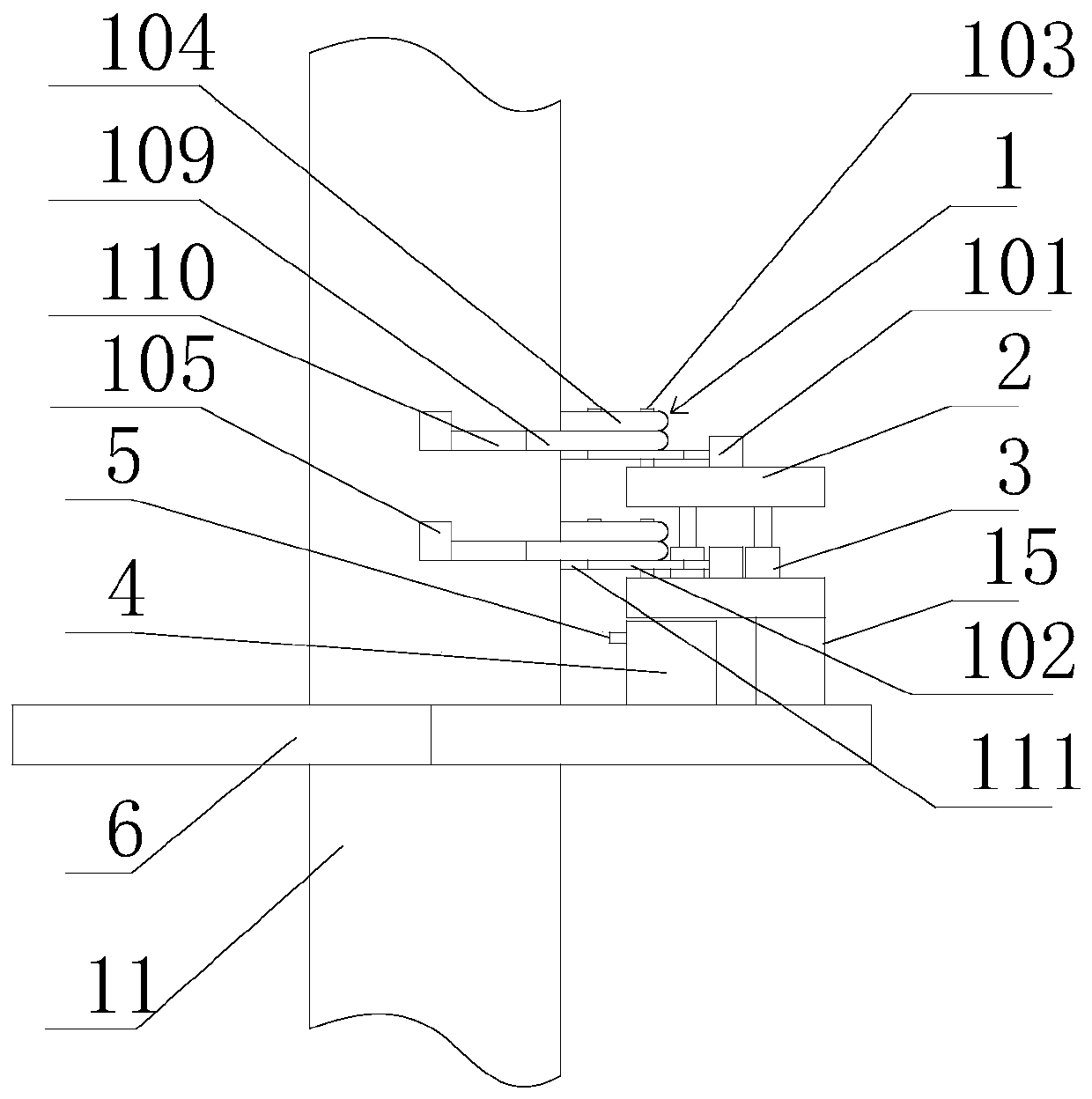
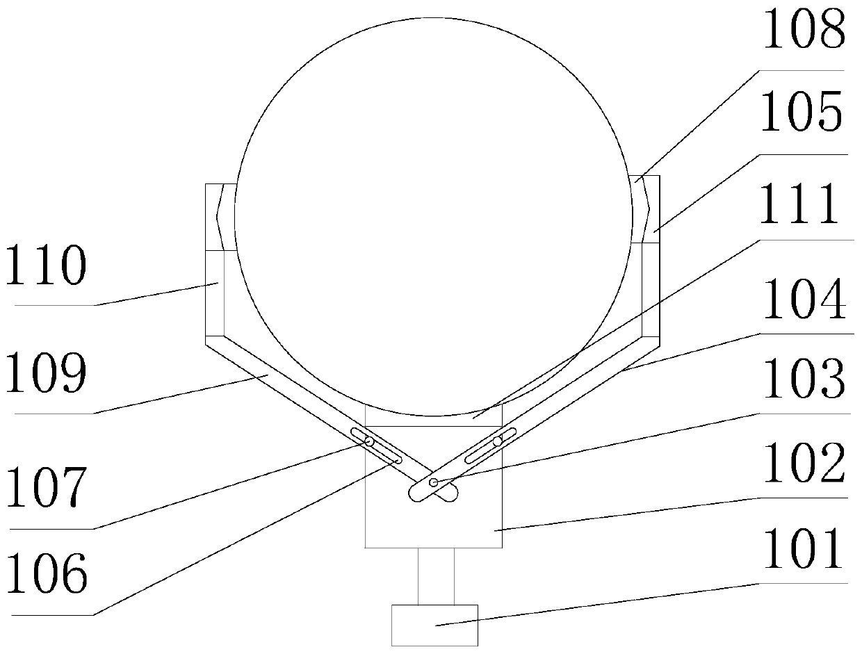
[0027] Such as figure 1 with figure 2 As shown, this embodiment includes a sprayer 4, two clamping assemblies 1, two bearing plates 2 and at least one lifting drive cylinder 3, the lifting drive cylinder 3 is vertically arranged, and the two bearing plates 2 are coaxially arranged , the lift drive cylinder 3 is fixed on one of the load plates 2, and the output end of the lift drive cylinder 3 is connected to the other load plate 2, the sprayer 4 is fixed on the load plate 2 below, and the two described The clamping components 1 are respectively fixed on the upper surfaces of the two bearing plates 2, and the clamping components 1 are used to clamp on the pier 11 to fix the bearing plate 2 and the spraying machine 4; when in use, one of the clamping components 1 is closed and clamped On the pier 11, another clamping component 2 is released, and the lifting drive cylinder 3 is controlled to expand and contract, so that the loosened clamping component 2 can be lifted and lowere...

Embodiment 2

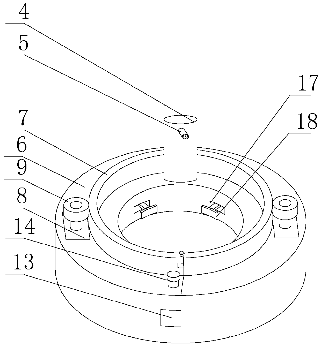
[0030] In order to enable the device to realize ring-shaped painting of the pier 11, the present embodiment is further limited on the basis of embodiment 1; as image 3 with Figure 4 As shown, two semi-annular plates 6 are also included in the present embodiment, wherein one semi-annular plate 6 is connected to any one of the bearing plates 2 through a connecting block 15, and the end surface of each semi-annular plate 6 is provided with a first protrusion. 13, the end face of the other semicircular plate 6 is provided with a first groove, the first protrusion 13 is matched with the first groove, and the first protrusion 13 is provided with a first threaded hole. A groove side wall is provided with the second threaded hole, and the stop bolt 14 passes through the first threaded hole and the second threaded hole to fix the two semicircular ring plates 6 to form a full circular annular plate; The upper surface of the ring plate 6 is provided with a semicircular trapezoidal gro...


PUM


Abstract

An automatic paint spraying device of a pier comprises a spraying machine, two clamping assemblies, two bearing plates and at least one lifting drive air cylinder. The lifting drive air cylinder is arranged vertically and is fixed to one bearing plate, and the output end of the lifting drive air cylinder is connected with the other bearing plate. The spraying machine is fixed to one bearing plate.The two clamping assemblies are fixed to the two bearing plates correspondingly, and the clamping assemblies are used for being clamped on the pier to fix the bearing plates and the spraying machine.During use, one clamping assembly is clamped on the pier in a closed manner, the other clamping assembly is loosened, the lifting drive air cylinder is controlled to stretch and contract, the loosened clamping assembly ascends and descends, the two clamping assemblies are clamped and loosened alternately, the spraying machine is driven to ascend and descend, a spray gun of the spraying machine iscontrolled to be opened and closed, and the spraying machine can spray the pier in the process of ascending and descending; and paint spraying can be automatically carried out on the pier, the paintspraying efficiency can be improved, and construction safety performance can be improved.

Description

technical field [0001] The invention relates to the field of paint spraying equipment, in particular to an automatic paint spraying device for bridge piers. Background technique [0002] Bridges refer to structures erected on rivers, lakes and seas to allow vehicles and pedestrians to pass smoothly. In order to adapt to the modern high-speed development of the transportation industry, bridges are also extended to cross mountains, poor geological conditions or meet other traffic needs to erect buildings that make traffic more convenient. In the field of road transportation, bridges are indispensable. With the development of society, There are more and more bridges being built, and there are countless large, medium and small bridges. The main body of the bridge is supported by the pier, which is a column. The pier of the bridge is relatively high. The cement used for the pier is generally Portland cement. Under long-term exposure to the sun and rain, CaSiO3 will undergo a che...

Claims


Application Information

Patent Timeline
IPC IPC(8): B05B15/62B05B13/04E01D22/00
CPCB05B13/041B05B13/0426B05B15/62E01D22/00
Inventor 李义政
Owner 四川精点企业管理有限公司
Learn More