Multi-joint omnidirectional motion pipeline robot

A pipeline robot and multi-joint technology, applied in the field of robotics, can solve the problems of walking foot gait planning and the difficulty of coordinated motion control between joints

Pending Publication Date: 2019-08-27
ZHEJIANG TIANHUANG TECH INDAL
View PDF0 Cites 1 Cited by
  • Summary
  • Abstract
  • Description
  • Claims
  • Application Information

AI Technical Summary

Problems solved by technology

The walking foot has two functions of support and driving at the same time, and it can theoretically adapt to various shapes of pipes, but there are certain difficulties in the gait planning and joint motion control of the walking foot.

Method used


Image

  • Multi-joint omnidirectional motion pipeline robot
  • Multi-joint omnidirectional motion pipeline robot
  • Multi-joint omnidirectional motion pipeline robot

Examples


Embodiment 1

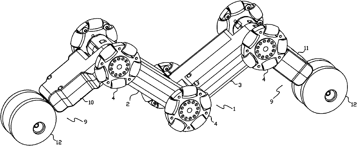
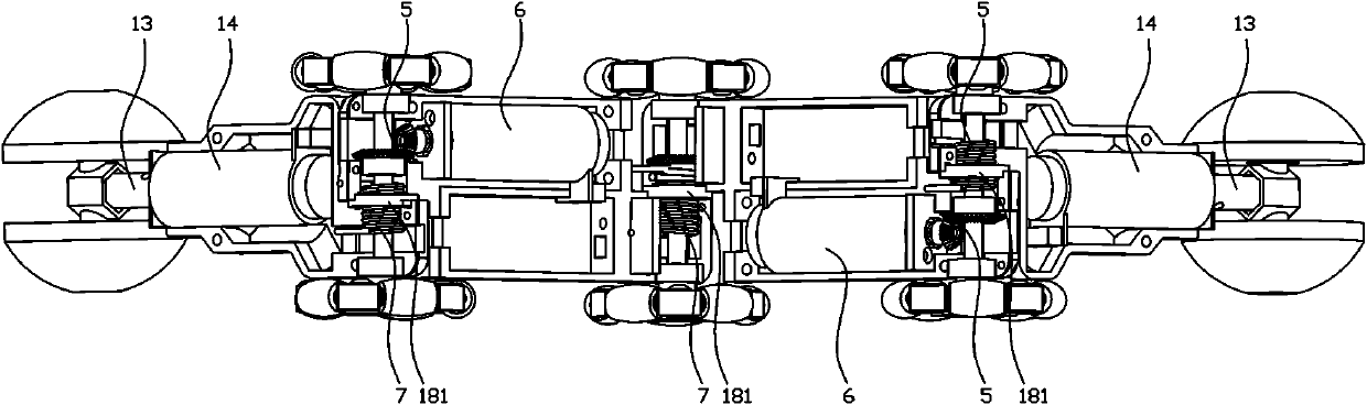
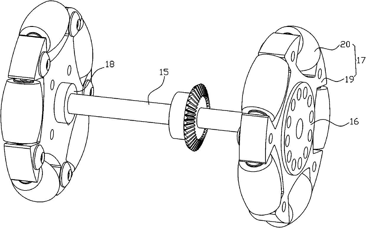
[0038] Such as Figure 1-8 As shown, the multi-joint omnidirectional motion pipeline robot of the present invention includes an intermediate joint 1 and a guide joint 9 . The intermediate joint 1 is mainly composed of the first shell 2 and the second shell 3 hinged through the inner ends, the hinges of the first shell 2 and the second shell 3 and the first shell 2, The outer ends of the second housing 3 are respectively provided with wheel assemblies 4 . The wheel assemblies 4 on the outer ends of the first housing 2 and the second housing 3 are respectively connected to the driving motor 6 through the bevel gear pair 5 . Described bevel gear pair 5 is made up of active conical wheel and passive conical wheel that mesh with each other, and described active conical wheel is connected with driving motor 6, and described passive conical wheel is fixed with the axle of described wheel assembly 4. couplet. A torsion spring 7 is provided between the first housing 2 and the second...

Embodiment 2

[0049] Such as Figure 9 As shown, the multi-joint omnidirectional motion pipe robot of the present invention, between the first shell 2 and the second shell 3, between the third shell 10 and the first shell 2, the fourth Between the housing 11 and the second housing 3 there are tension springs 8 respectively, and the tension springs 8 are fixedly connected to the adjacent housings. The rest of the structure is the same as the multi-joint omnidirectional motion pipeline robot described in Embodiment 1. The robot finally forms a W-shaped multi-joint configuration structure through the tension spring 8 .

[0050] Further, the first shell 2 , the second shell 3 , the third shell 10 , and the fourth shell 11 are all provided with expansion joints 24 . The expansion joint 24 realizes the change of the length of the pipeline robot under the drive of the linear motor. The structure of the expansion joint 24 is a known technology, so it will not be repeated here.


PUM


Abstract

The invention discloses a multi-joint omnidirectional motion pipeline robot. According to the technical scheme adopted by the invention, the multi-joint omnidirectional motion pipeline robot comprisesa middle joint which is mainly formed by hinging a first housing and a second housing, wherein a hinged position of the first housing and the second housing, the outer end of the first housing and the outer end of the second housing are separately equipped with wheel assemblies; the wheel assemblies at the outer end of the first housing and the outer end of the second housing are at least connected to a drive motor through bevel gear pairs; a torsion spring or a tension spring is arranged between the first housing and the second housing; and through applied force of the torsion spring or thetension spring, a V-shaped structure is arranged between the first housing and the second housing. The multi-joint omnidirectional motion pipeline robot has the beneficial effects: a W-shaped multi-joint-form structure, a spherical steering wheel, a universal drive wheel, and the like are delicately combined, so that a pipeline robot drive mechanism with multi-tube-diameter adaption ability and universal motion ability is used to replace a common pipeline robot caterpillar band type and common wheel type drive mechanism, and therefore, the pipeline robot has universal motion ability, and provides structure advantages for pipeline robot obstacle-avoiding and motion posture regulating.

Description

technical field [0001] The invention belongs to the technical field of robots, and in particular relates to a pipeline robot. Background technique [0002] Pipeline robots mainly include wheel type, crawler type, peristaltic type, and crawling type in terms of driving methods. Now the pipeline robots with various driving modes at home and abroad are analyzed. [0003] Wheel-type pipeline robots: Wheel-type walking mechanisms are widely used in pipeline robots, and can be divided into two types: wheel-type and support-wheel-type from the structure. The wheeled pipeline robot walks on the surface of the inner wall of the pipeline, similar to the way a vehicle walks on the ground. It has the advantages of simple structure, continuous and stable walking, and flexible movement in the pipeline. However, this kind of pipeline robot mostly relies on its own weight to provide positive pressure, and can only move at the bottom of the pipeline placed at a certain angle, so it is dif...

Claims


Application Information

Patent Timeline
IPC IPC(8): F16L55/32
CPCF16L55/32
Inventor 黄华圣徐高欢邬志明章群芳
Owner ZHEJIANG TIANHUANG TECH INDAL
Why Eureka
Try Eureka