
Disc type multi-station compressing rotating clamp

A pressing, rotating, multi-station technology, applied in the direction of manufacturing tools, clamping, positioning devices, etc., can solve the problems of a large number of workers, the difficulty of ensuring the stability of signal transmission, the accuracy of rotation, and the accuracy of lock cylinder products, etc., to achieve The effect of precise rotation positioning

Active Publication Date: 2015-04-22
CHONGQING WNC INTELLIGENT EQUIP
View PDF7 Cites 7 Cited by
  • Summary
  • Abstract
  • Description
  • Claims
  • Application Information

AI Technical Summary

Problems solved by technology

If it is arranged according to a single process, it will not only require a large number of workers to coordinate operations, but also the multiple clamping of the lock cylinder workpiece will make it difficult to guarantee the accuracy of the final lock cylinder product.
At present, a special disc machine is generally used to clamp the lock cylinder workpiece. Although it can meet the use requirements to a certain extent, it is difficult to guarantee the stability of signal transmission and the rotation accuracy of the fixture between multiple stations, and it is impossible to realize the revolution of the large disc. Therefore, there is an urgent need for a fixture that can not only compress the lock cylinder workpiece, but also realize the rotation of the lock cylinder workpiece between multiple stations.

Method used


Image

  • Disc type multi-station compressing rotating clamp
  • Disc type multi-station compressing rotating clamp

Examples


Embodiment Construction

[0021] The present invention will be further described below in conjunction with the accompanying drawings and specific embodiments, so that those skilled in the art can better understand the present invention and implement it, but the examples given are not intended to limit the present invention.

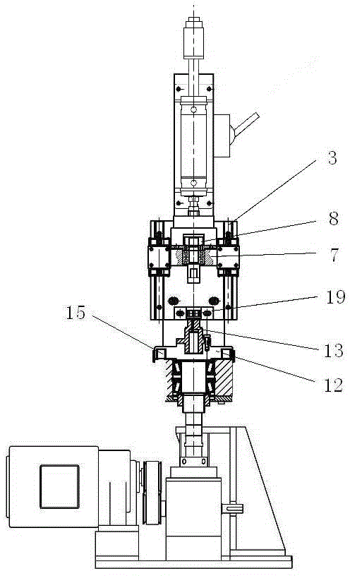
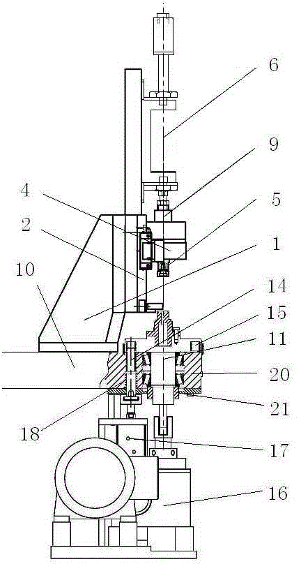
[0022] Such as figure 1 As shown, it is a structural schematic diagram of an embodiment of the disc-type multi-station pressing and rotating fixture of the present invention. The disc-type multi-station pressing and rotating jig of this embodiment includes a support 1, a pressing mechanism is provided on the support 1, and a rotating mechanism is provided below the support 1.

[0023] The pressing mechanism of this embodiment includes a guide rail slide plate 2 fixedly installed on the bracket 1, the guide rail slide plate 2 is provided with a linear guide rail 3 in the vertical direction, and a pressure head mounting seat 4 slidingly matched with it is installed on the linear gui...


PUM


Abstract

The invention discloses a disc type multi-station compressing rotating clamp. The disc type multi-station compressing rotating clamp comprises a support; a compressing mechanism is arranged above the support, and a rotating mechanism is arranged below the support; the compressing mechanism comprises a guide rail sliding plate, and linear guide rails are arranged on the guide rail sliding plate; a pressing head mounting base is arranged on the linear guide rails, and a rotating pressing head is arranged on the bottom face of the pressing head mounting base; and an adjustable stroke air cylinder for driving the pressing head mounting base to slide along the linear guide rails is fixedly arranged on the support. The rotating mechanism comprises a clamping base, and a rotating connecting shaft is arranged in the clamping base; and a rotating positioning disc is arranged at the upper end, stretching out of the clamping base, of the rotating connecting shaft, and a workpiece clamp corresponding to the rotating pressing head is arranged on the rotating positioning disc. Pin holes are formed in the clamping base, and positioning pins are arranged in the pin holes; a plurality of positioning pin holes matched with the positioning pins are formed in the bottom face of the rotating positioning disc at intervals; and a driving mechanism for driving the rotating connecting shaft to rotate and a pin inserting and pulling mechanism for driving the positioning pins to be inserted into the positioning pin holes or pulled out of the positioning pin holes are arranged below the clamping base.

Description

technical field [0001] The invention belongs to the technical field of mechanical tooling fixtures, and in particular relates to a disc-type multi-station pressing rotary fixture which is used on a disc-type automatic line and can drive the workpiece to rotate at multiple positions after automatically pressing the workpiece. Background technique [0002] In the current lock cylinder processing industry, because the processing procedures of the lock cylinder are various, and multiple surfaces of the lock cylinder workpiece need to be processed. If it is arranged according to a single process, not only a large number of workers need to cooperate to operate, but also the multiple clamping of the lock cylinder workpiece will make it difficult to guarantee the accuracy of the final lock cylinder product. At present, a special disc machine is generally used to clamp the lock cylinder workpiece. Although it can meet the use requirements to a certain extent, it is difficult to guara...

Claims


Application Information

Patent Timeline
IPC IPC(8): B23Q3/00B23Q7/02
CPCB23Q3/00B23Q3/08
Inventor 华亮亮张永灿黄刚强
Owner CHONGQING WNC INTELLIGENT EQUIP
Learn More