Large stroke pushing device

A pushing device and large-stroke technology, which is applied in the direction of transportation and packaging, conveyor objects, etc., can solve the problems of short pushing stroke of the pushing rod and unstable movement of the pushing rod

Inactive Publication Date: 2015-04-22
南京科院新派设计有限公司
View PDF0 Cites 19 Cited by
  • Summary
  • Abstract
  • Description
  • Claims
  • Application Information

AI Technical Summary

Problems solved by technology

[0003] In the automatic production line, the products produced are usually sent out automatically, and there is no need to manually take out the product. The discharge device used in the existing automatic production line is usually controlled by a cylinder. The piston rod of the cylinder is connected to the push rod, and the push rod Push the product out, but the push rod can push out less products at a time, the movement of the push rod is unstable, and the push stroke of the piston rod push rod is short

Method used


Image

  • Large stroke pushing device

Examples


Embodiment Construction

[0012] The present invention will be described in further detail below by means of specific embodiments:

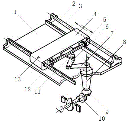
[0013] The reference signs in the drawings of the description include: base plate 1, fixed rack 2, guide rod 3, pusher plate 4, sliding rod 5, connecting rod 6, crank 7, vertical shaft 8, driven bevel gear 9, driving bevel gear 10. Sliding block 11, gear 12, oil filling hole 13.

[0014] Such as figure 1 As shown, a large-stroke pushing device includes a motor, a bottom plate 1, a driving bevel tooth 10, a driven bevel tooth 9, a vertical shaft 8, a crank 7, a connecting rod 6, a pushing plate 4, a fixed rack 2, and a gear 12 , guide rod 3, sliding block 11 and sliding rod 5, vertical shaft 8 is connected in rotation on the base plate 1, the lower end of vertical shaft 8 is connected with driven bevel gear 9, the upper end is fixedly connected with one end of crank 7, and active bevel gear 10 is connected with the output end of the motor, One end of the connecting rod 6...


PUM


Abstract

The invention discloses a large stroke pushing device which comprises a motor, a bottom plate, a driving bevel gear, a driven bevel gear, a vertical shaft, a crank, a connecting rod, a pushing plate, fixed racks, gears, guide rods, a sliding block and a sliding rod. The vertical shaft is rotatably connected with the bottom plate, the lower end of the vertical shaft is connected with the driven bevel gear, the upper end of the vertical shaft is fixedly connected with one end of the crank, the driving bevel gear is connected with the output end of the motor, one end of the connecting rod is hinged to one end of the crank, the other end of the connecting rod is hinged to the sliding block, and the fixed racks and the guide rods which are each arranged in a symmetrical mode are arranged at the two sides of the vertical shaft respectively; the sliding rod is connected with one side of the pushing plate, the sliding block is connected with the sliding rod in a sliding mode, two ends of the sliding rod are provided with the gears, the gears arranged at the two ends of the sliding rod are meshed with the fixed racks arranged at the two sides of the vertical shaft respectively, and the two sides of the pushing plate are connected with the guide rods at the two sides of the vertical shaft respectively. By means of the large stroke pushing device, more products can be pushed out in one time and the process of pushing material is stable.

Description

technical field [0001] The invention relates to a large stroke pushing device. Background technique [0002] The automatic production line is a production system that automatically completes all or part of the manufacturing process of a product by connecting a group of automatic machine tools and auxiliary equipment in accordance with the process sequence by a workpiece transmission system and a control system, referred to as an automatic line. The automatic production line is the process of automatically operating or controlling according to the prescribed procedures or instructions without human intervention, and its goal is "stable, accurate and fast". Automation technology is widely used in industry, agriculture, military, scientific research, transportation, commerce, medical care, services and households. The use of automatic production lines can not only liberate people from heavy physical labor, some mental work, and harsh and dangerous working environments, but als...

Claims


Application Information

Patent Timeline
Patent Type & Authority Applications(China)
IPC IPC(8): B65G47/82
Inventor 周建勋
Owner 南京科院新派设计有限公司
Why Eureka
Try Eureka