Electromagnetic type conveying device for blades

A transmission device and electromagnetic technology, applied in the field of electromagnetic transmission device, can solve the problems of hidden dangers and high equipment costs, and achieve the effects of reducing hidden dangers, low cost and simple structure

Inactive Publication Date: 2015-04-22
CHONGQING SHANNENG INSTR
View PDF0 Cites 3 Cited by
  • Summary
  • Abstract
  • Description
  • Claims
  • Application Information

AI Technical Summary

Problems solved by technology

[0004] The present invention mainly solves the problems of potential safety hazards or high equipment costs in the process of blade separation and transmission in the prior art

Method used


Image

  • Electromagnetic type conveying device for blades

Examples


Embodiment Construction

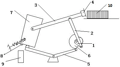
[0013] The reference signs in the description of the drawings are: linkage plate 1, push rod 2, feed rod 3, electromagnet 4, swing rod 5, cam 6, support block 7, touch switch 8, convex part 9, blade 10.

[0014] Such as figure 1 As shown, the technical solution provides an electromagnetic transmission device for blades, including a transfer device and a lever-type transmission device, and the transfer device includes a linkage mechanism composed of a linkage plate 1, a push rod 2 and a feed rod 3, The two ends of the push rod 2 are respectively hinged on the linkage plate 1 and the feed rod 3 , and the end of the feed rod 3 is fixedly equipped with an electromagnet 4 . The lever type transmission device includes a swing rod 5, a cam 6 and a support block 7, the swing rod 5 is in a curved structure, and its inflection point is a hinge point, and the two ends of the swing rod 5 are respectively connected with the cam 6 and the support block 7, One end of the feeding rod 3 is hi...


PUM


Abstract

The invention relates to the field of blade conveying, in particular to an electromagnetic type conveying device for blades. The conveying device comprises a rack, a transferring device and a lever type transmission device. A transmission shaft is arranged on the rack, and the transferring device comprises a connecting rod mechanism composed of a linkage plate, a pushing rod and a feeding rod; the two ends of the pushing rod are hinged to the linkage plate and the feeding rod, and an electromagnet is arranged at the end of the feeding rod; the lever type transmission device comprises a swing rod, a cam and a supporting block; a hinge point is arranged in the middle of the swing rod, and the two ends of the swing rod are connected with the cam and the supporting block respectively; one end of the feeding rod is hinged to the supporting block, and a point contact switch is arranged on the lower bottom face of the supporting block; a protruding piece in contact with the point contact switch is arranged below the supporting block; and the cam and the linkage plate are coaxially and fixedly connected with the transmission shaft of the rack. Through the implementation, the conveying device mainly solves the problem that in the prior art, potential safety hazard or high equipment cost exists in the blade separation conveying process.

Description

technical field [0001] The invention is applied in the field of blade transmission, and in particular relates to an electromagnetic transmission device for blades. Background technique [0002] At present, we often use different types of blades in our daily life, such as fruit knives, eyebrow trimming knives, etc. Before leaving the factory, the blades need to be processed and packaged to avoid causing harm to others harm. [0003] In the prior art, when processing blades, manual transmission is usually adopted, that is, a stack of blades is separated manually, and then the separated blades are put into the sub-processing station one by one for the next step of processing, but due to The blade is sharper, and it will scratch the human body if you are not careful, especially after the staff has worked for a long time, the mental state is not good, and it is more likely to cause safety accidents. Some are clamped by manipulators. Since the blades are thinner, equipment with ...

Claims


Application Information

Patent Timeline
Patent Type & Authority Applications(China)
IPC IPC(8): B65G47/92
Inventor 李立光
Owner CHONGQING SHANNENG INSTR
Why Eureka
Try Eureka