Gear mechanism based self-rotation blade impeller

A blade impeller and gear mechanism technology, applied to engines, mechanical equipment, wind turbines, etc., can solve the problems of low energy capture efficiency and difficult self-starting, achieve good self-starting performance, reduce headwind resistance, and increase rotational torque.

Inactive Publication Date: 2015-04-22
NORTHWESTERN POLYTECHNICAL UNIV
View PDF6 Cites 5 Cited by
  • Summary
  • Abstract
  • Description
  • Claims
  • Application Information

AI Technical Summary

Problems solved by technology

[0014] In order to overcome the problems of difficult self-starting of lift-type vertical-axis impellers and low energy capture efficiency of drag-type vertical-axis

Method used


Image

  • Gear mechanism based self-rotation blade impeller
  • Gear mechanism based self-rotation blade impeller
  • Gear mechanism based self-rotation blade impeller

Examples


Embodiment Construction

[0030] The present invention will now be further described in conjunction with the embodiments and drawings:

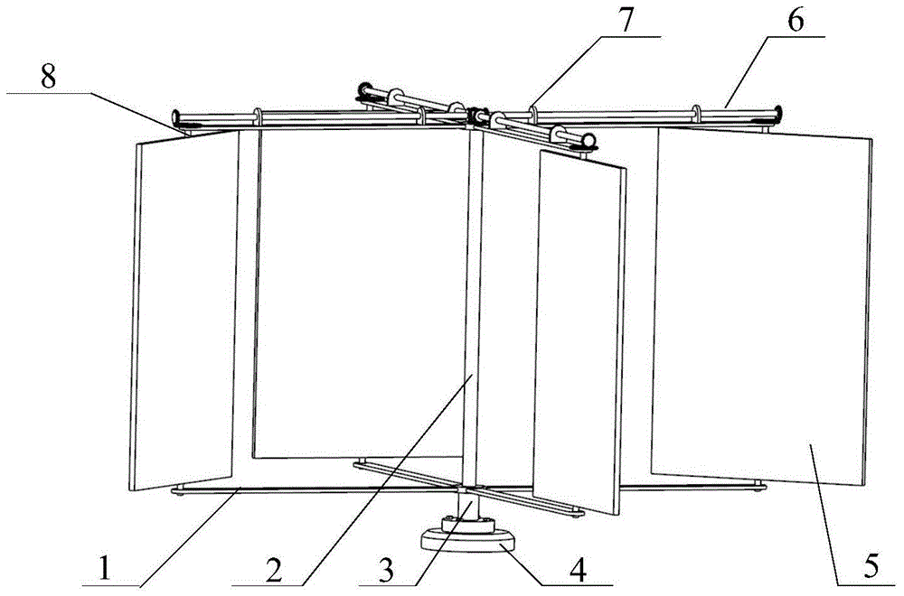
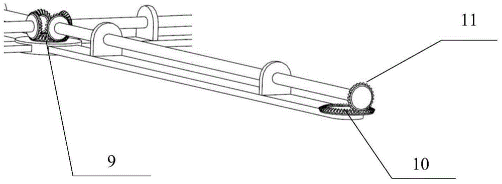
[0031] A self-rotating blade impeller device based on a gear mechanism, which is mainly composed of a rotating cross bracket 1, four blades 5, a central shaft 2, a base 4, a primary bevel gear 9, four secondary bevel gears 10, and eight transmission gears 11 And four drive shafts 6.

[0032] The bottom of the central shaft 2 is fixedly connected with the base 4, and a boss 3 is provided on the upper end of the base 4 to support the cross bracket 1. The length of the central shaft 2 above the boss 3 is slightly longer than the length of the blade 5.

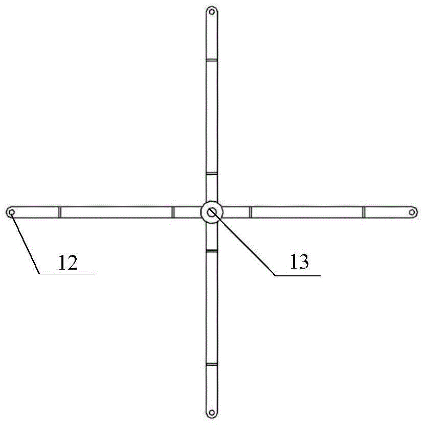
[0033] The rotating cross frame 1 is composed of an upper bracket and a lower bracket. Such as image 3 As shown, the lower bracket has a cross shape as a whole, and a central shaft mounting hole 13 is provided in the center of the cross shape. The hole diameter is between the diameter of the central shaft and the diameter of ...


PUM


Abstract

The invention relates to a gear mechanism based self-rotation blade impeller. The gear mechanism based self-rotation blade impeller is mainly formed by a rotating cross support, four blades, a center shaft, a base, a primary bevel gear, four secondary bevel gears, eight transmission gears and four transmission shafts.

Description

Technical field [0001] The invention belongs to the technical field of wind power generation, and in particular relates to a self-rotating blade impeller based on a gear mechanism. Background technique [0002] Energy is the driving force and guarantee for the development and progress of human society. In recent years, with the rapid development of the global economy, conventional energy sources such as coal, oil, and natural gas have been rapidly and massively consumed. This puts human beings not only facing the pressure of depleting resources, but also threatened by the deteriorating environment. Energy and environmental protection have become urgent issues that need to be resolved urgently for human survival and development. As a clean and environmentally friendly new energy source, wind power neither consumes limited coal resources nor consumes precious underground wind resources. It is more conducive to the sustainable development of the national economy. In all regions of ...

Claims


Application Information

Patent Timeline
IPC IPC(8): F03D3/06
CPCY02E10/74
Inventor 宋保维施瑶毛昭勇丁文俊田文龙安新宇
Owner NORTHWESTERN POLYTECHNICAL UNIV
Why Eureka
Try Eureka