Gas monitoring probe and gas monitoring system

A gas monitoring and gas technology, applied in the direction of color/spectral characteristic measurement, sampling device, etc., can solve the problems of untimely cleaning of dust impurities, detection result errors, etc., to achieve the effect of ensuring cleaning, eliminating errors, and avoiding detection errors

Inactive Publication Date: 2015-04-22
GL TECH CO LTD
View PDF11 Cites 9 Cited by
  • Summary
  • Abstract
  • Description
  • Claims
  • Application Information

AI Technical Summary

Problems solved by technology

[0004] The purpose of the present invention is to provide a gas monitoring probe to solve the problem in the prior art that if the dust and impurities inside the collection device are not cleaned up in time after a long time of detection, the error of the detection result will be caused; the present invention also provides a Gas Monitoring System

Method used


Image

  • Gas monitoring probe and gas monitoring system
  • Gas monitoring probe and gas monitoring system
  • Gas monitoring probe and gas monitoring system

Examples


Embodiment 1

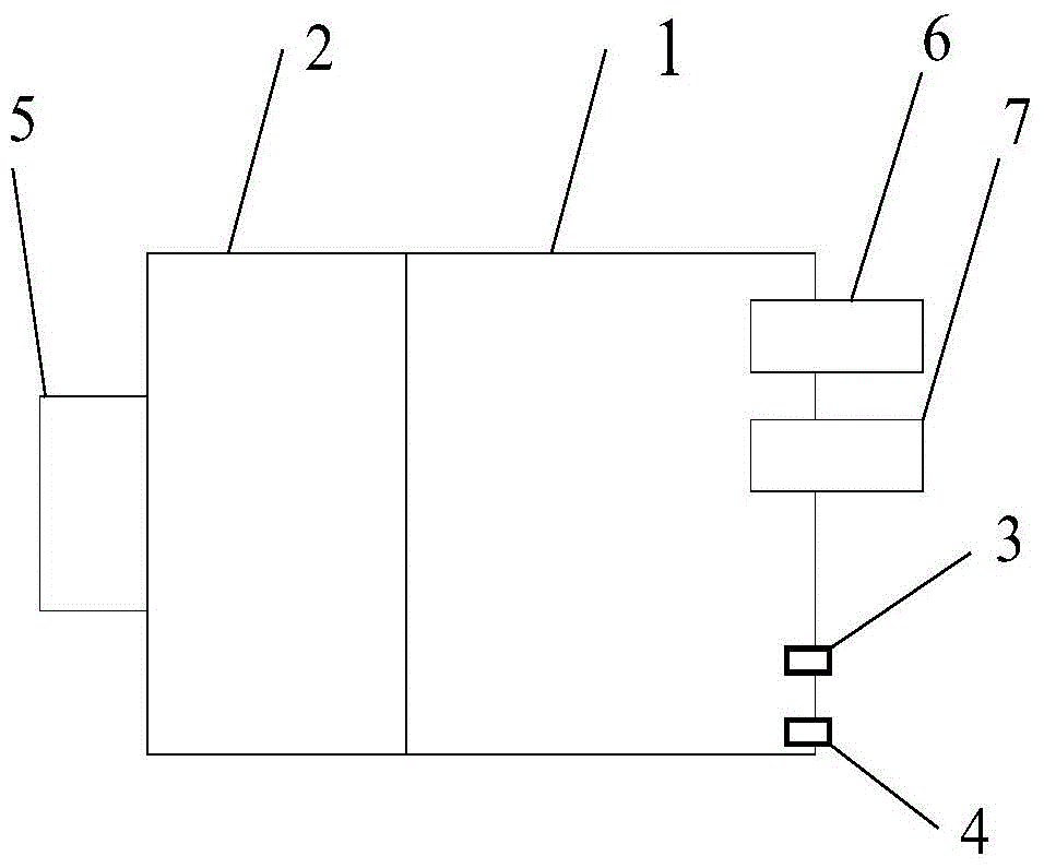
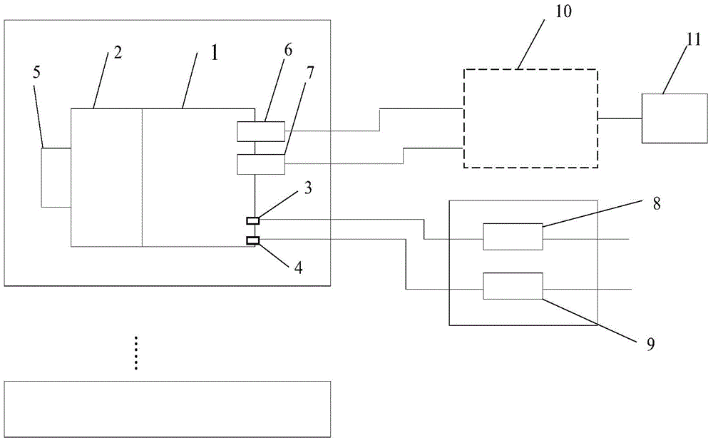
[0025] Such as figure 1 Shown is a schematic diagram of the structure of the gas monitoring probe. The gas monitoring probe includes a sampling inner cavity 1, the sampling inner cavity 1 communicates with the filter device 2 through a communication airway, and the filter device 2 has an air inlet 5; The gas to be tested is filtered to prevent dust and impurities from being sampled in the inner chamber 1, causing errors in the test results.

[0026] The sampling inner cavity 1 has a purge inlet 3 and an air extraction outlet 4 .

[0027] After a long period of detection, it is inevitable that a certain amount of tiny dust and impurities will accumulate in the sampling inner cavity 1. When the sampling inner cavity 1 is purged and cleaned, the purge air inlet 3 blows the cleaning gas into the sampling inner cavity 1, and the cleaning gas The dust and impurities in the sampling inner cavity 1 are blown up, and the cleaning gas blown into the sampling inner cavity 1 by the purg...

Embodiment 2

[0030] Such as figure 1 Shown is a schematic diagram of the structure of the gas monitoring probe. The gas monitoring probe includes a sampling inner cavity 1, the sampling inner cavity 1 communicates with the filter device 2 through a communication airway, and the filter device 2 has an air inlet 5; The gas to be tested is filtered to prevent dust and impurities from being sampled in the inner chamber 1, causing errors in the test results.

[0031] The sampling inner cavity 1 has a purge inlet 3 and an air extraction outlet 4 .

[0032] After a long period of detection, it is inevitable that a certain amount of tiny dust and impurities will accumulate in the sampling inner cavity 1. When the sampling inner cavity 1 is purged and cleaned, the purge air inlet 3 blows the cleaning gas into the sampling inner cavity 1, and the cleaning gas The dust and impurities in the sampling inner cavity 1 are blown up, and the cleaning gas blown into the sampling inner cavity 1 by the purg...


PUM


Abstract

The invention relates to a gas monitoring probe and a gas monitoring system. The gas monitoring probe comprises a sampling inner cavity, the sampling inner cavity is provided with a purging air inlet and an exhaust air outlet, the purging air inlet is used for conducting purging cleaning on the sampling inner cavity, and the exhaust air outlet is used for exhausting gas in the sampling inner cavity. The gas monitoring system comprises the gas monitoring probe, the purging air inlet is connected with a purging pipeline, and the exhaust air outlet is connected with an exhaust pipeline. The sampling inner cavity is subjected to purging cleaning through the purging air inlet, then the gas in the sampling inner cavity can be exhausted in time through the exhaust air outlet, dust and impurities generated in the sampling inner cavity due to accumulation for a long time are effectively cleaned, the dust and impurities can be discharged thoroughly, the cleanliness of the sampling inner cavity is guaranteed, and the influence on testing results and errors are avoided.

Description

technical field [0001] The invention relates to a gas monitoring probe and a gas monitoring system, belonging to the technical field of gas monitoring. Background technique [0002] Air pollution is becoming more and more serious, the country has higher and higher environmental protection requirements for power plants, and the detection of NOx emissions from power plants is becoming more and more stringent. In order to reduce NOx emissions, power plants need to use ammonia to chemically react NOx to reduce Environmental pollution, in order to ensure the right amount of ammonia gas added, it is necessary to monitor the concentration of ammonia gas after the reaction in the flue. [0003] In the prior art, the application number is 201310548045.8, and the title of the invention is "Sulfur Hexafluoride Switch On-line Monitoring System", which discloses a gas monitoring system, including a sampling device and a gas extraction pipe. The gas sampling device is connected to a laser...

Claims


Application Information

Patent Timeline
Patent Type & Authority Applications(China)
IPC IPC(8): G01N21/31G01N1/24
Inventor 赵彤宇朱海龙石云鹏高华周正
Owner GL TECH CO LTD
Why Eureka
Try Eureka