Log-periodic dipole antenna loaded with rectangular coupled resonators

A technology of logarithmic period and vibrator antenna, which is applied in the field of communication, can solve the problems of inconvenient processing and use, large antenna size, etc., and achieve the effect of improving utilization rate, large bandwidth, and increasing bandwidth

Active Publication Date: 2015-04-22
昆山亿趣信息技术研究院有限公司
View PDF8 Cites 6 Cited by
  • Summary
  • Abstract
  • Description
  • Claims
  • Application Information

AI Technical Summary

Problems solved by technology

[0005] The current research hotspots of the logarithmic periodic dipole antenna are mainly focused on increasing the bandwidth and reducing the lower cut-off frequency by changing the structure of the oscillator at the low frequency end. Changes in equal proportions, when the cut-off frequency is low, the size of the antenna is larger, which brings inconvenience to processing and use

Method used


Image

  • Log-periodic dipole antenna loaded with rectangular coupled resonators
  • Log-periodic dipole antenna loaded with rectangular coupled resonators
  • Log-periodic dipole antenna loaded with rectangular coupled resonators

Examples


Embodiment Construction

[0031] The embodiments of the present invention are described in detail below in conjunction with the accompanying drawings: this embodiment is implemented on the premise of the technical solution of the present invention, and detailed implementation methods and specific operating procedures are provided, but the protection scope of the present invention is not limited to the following the described embodiment.

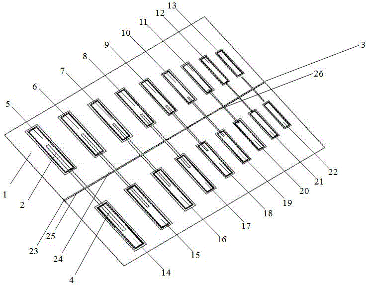
[0032] Such as figure 1 As shown, this embodiment includes: a dielectric board 1 that plays a supporting role, and an input port 23, the input port is connected to the front, back and center of the dielectric board respectively, wherein the center of the dielectric board is connected to the signal of the input port, the medium The front and back of the board and the ground connection of the input port.

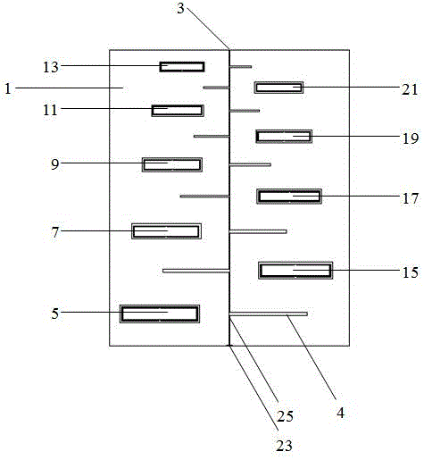
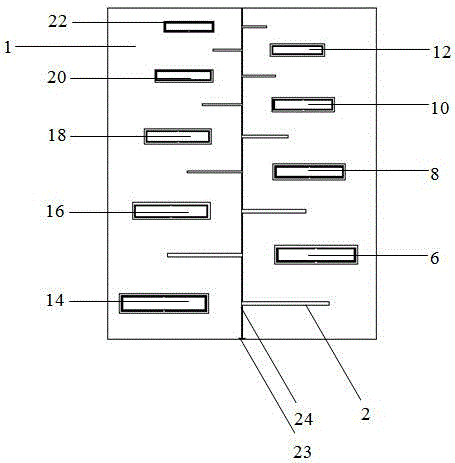
[0033] Such as figure 2 As shown, the front side of the dielectric board 1 described in this embodiment includes: a first transmission line unit 25, a first logari...


PUM


Abstract

The invention belongs to the technical field of communication and particularly provides a log-periodic dipole antenna loaded with rectangular coupled resonators. The antenna comprises a pair of log-periodic dipole antenna arrays, a pair of rectangular coupled resonator arrays and an input port. The obverse side of a dielectric slab is provided with one log-periodic dipole array, one rectangular coupled resonator array and a ribbon feeder, wherein the rectangular coupled resonators correspond to dipoles on the reverse side of the dielectric slab in position to form coupled feeding. The reverse side of the dielectric slab is provided with the other log-periodic dipole array, the other rectangular coupled resonator array and a ribbon feeder, and the reverse side of the dielectric slab and the obverse side of the dielectric slab are distributed symmetrically in structure. The center of the dielectric slab is provided with a ribbon feeder. According to the log-periodic dipole antenna loaded with the rectangular coupled resonators, by loading a traditional log-periodic dipole antenna with the rectangular coupled resonator arrays, the advantages of widened frequency band, low cut-off frequency and compact size are achieved.

Description

technical field [0001] The invention belongs to the technical field of communication, and in particular relates to a logarithmic period dipole antenna loaded with a novel structure. Background technique [0002] The logarithmic periodic antenna was proposed in 1957. It is a broadband non-frequency variable antenna. Its basic idea is that the antenna is proportional to a certain scale factor After the transformation is still equal to its original structure, the frequency of the antenna is and same time performance. Because of its wide frequency band and simple structure, it has been widely used in many fields rapidly. [0003] The main types of log-periodic antennas are log-periodic dipole antennas and monopole antennas, log-periodic resonant V-shaped antennas, and log-periodic helical antennas, among which the most common is the log-periodic dipole antenna. It can be used for point-to-point communication, and can also be used for scientific and technological digital s...

Claims


Application Information

Patent Timeline
Patent Type & Authority Applications(China)
IPC IPC(8): H01Q1/38H01Q1/50H01Q5/314H01Q5/40H01Q5/50
Inventor 卢修远杨国敏
Owner 昆山亿趣信息技术研究院有限公司
Why Eureka
Try Eureka