Synchronous rectification control method of switching power supply and control module thereof

A technology of synchronous rectification and switching power supply, applied in the field of synchronous rectification control method of switching power supply and its control module, can solve problems such as voltage spikes, influence driving voltage, reduce efficiency, etc., and achieve the effect of dynamic adjustment in time and improving reliability

Active Publication Date: 2015-04-22
MORNSUN GUANGZHOU SCI & TECH
View PDF8 Cites 4 Cited by
  • Summary
  • Abstract
  • Description
  • Claims
  • Application Information

AI Technical Summary

Problems solved by technology

[0018] (1) Different switching power supply topologies require different driving methods;
[0019] (2) In a certain period of time, the oscillation caused by the leakage inductance of the transformer, etc., affects the driving voltage and reduces the efficiency;
[0020] (3) There is a delay in the drive circuit, and the synchronous rectifier SR also has a turn-on delay. When the shutdown signal is received, there is a delay until the synchronous rectifier SR is turned off, causing the output voltage to pass through and not turn off in time. The synchronous rectifier SR supplies reverse power to the transformer winding or inductor, reducing efficiency, commonly known as reverse feeding
It can be seen from the waveform that for the three consecutive working cycles T1, T2, and T3 of the switching power supply, in the T1 cycle, the driving signal of the synchronous rectifier is set according to the conduction time of the previous cycle. The conduction time t1 is more appropriate, the conduction time of the body diode of the synchronous rectifier SRMOS meets the requirements of the dead time setting, in the T2 cycle, the conduction time t2 of the synchronous rectifier SRMOS is basically equal to t1; however, due to the , the duty cycle of the switching power supply changes suddenly, and the conduction time of the synchronous rectifier SRMOS is shortened. The tube has been turned on, and the above-mentioned backfilling phenomenon occurs
[0025] In the case of a small range of the shortened time, the backfeed phenomenon will lead to an increase in loss, and at the same time, a voltage spike will occur, and the voltage stress of the synchronous rectifier tube will increase; in the case of a large range of the shortened time, Due to the extremely high rise rate of the backfeed current, it is easy to cause the current stress of the main switch tube and synchronous rectifier tube to exceed the standard, which in turn leads to damage to the switching converter

Method used


Image

  • Synchronous rectification control method of switching power supply and control module thereof
  • Synchronous rectification control method of switching power supply and control module thereof
  • Synchronous rectification control method of switching power supply and control module thereof

Examples


Embodiment Construction

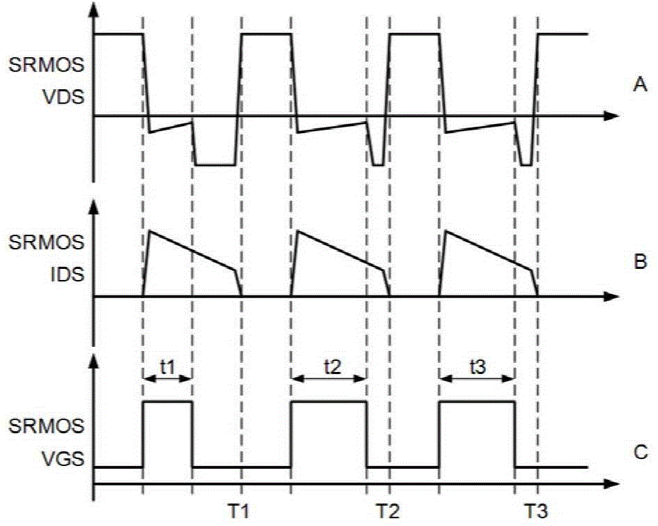
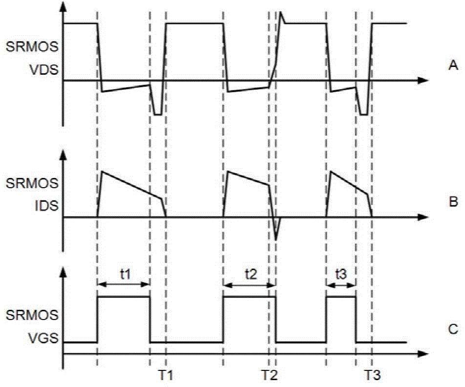
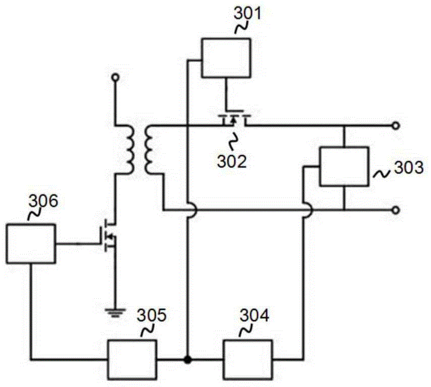
[0040] image 3 The schematic circuit diagram of the synchronous rectification control module of the switching power supply of the present invention is shown. The synchronous rectification works in the switching power supply. The synchronous rectification includes a synchronous rectification tube 302, which is applied to a synchronous rectification circuit device; it also includes an integrated circuit 301, and the integrated circuit 301 The control synchronous rectifier is a synchronous rectifier control module in the switching power supply. The switching power supply at least includes a sampling module 303, a feedback module 304, an isolated feedback circuit 305, and a main control circuit 306. The sampling module 303 samples the output signal of the switching power supply. The output signal may be a voltage signal or a current signal, and the output signal may be a voltage and The integrated signal of the current; the feedback module 304 receives the sampling signal, and ou...


PUM


Abstract

A synchronous rectification control method of a switching power supply mainly comprises the following step that a synchronous rectifier tube is controlled, wherein a feedback signal is received, and a dynamic judgment is made according to the feedback signal; when the feedback signal meets a set dynamic control reference value, a synchronous rectification control signal is output, and the synchronous rectifier tube is controlled to enter a dynamic working mode; a response is made directly to the feedback signal, so the synchronous rectifier tube starts to make an adjustment prior to a main power circuit, and then the synchronous rectifier tube has corresponding adjustment and control when the main power circuit has a sudden change; besides, when the main power circuit performs adjustment and control, the synchronous rectifier tube still has corresponding adjustment and control. Compared with the prior art, the backward flowing phenomenon caused by untimely adjustment of the synchronous rectifier tube under the condition that the duty ratio of the switching power supply has a sudden change is avoided, and the reliability of synchronous rectification control is improved substantially.

Description

technical field [0001] The invention relates to the technical field of switching power supplies, in particular to a synchronous rectification control method of a switching power supply and a control module thereof. Background technique [0002] Both industrial and civil use often need to change the AC voltage of various grids into DC, and most of them are isolated DC. With the further requirements of national standards for the working efficiency of various electrical appliances, the current requirements for converters in electrical appliances ( Generally, switching power supply) requires higher and higher conversion efficiency. Other countries also attach great importance to it. For example, the U.S. Department of Energy has formulated many standards to regulate the efficiency of switching power supplies. Among them, the 80PLUS series of standards have high requirements for the efficiency of power supplies. Power supplies with gold medals and above must use synchronous recti...

Claims


Application Information

Patent Timeline
IPC IPC(8): H02M1/08H02M7/217
CPCH02M1/08H02M7/217
Inventor 刘湘
Owner MORNSUN GUANGZHOU SCI & TECH
Why Eureka
Try Eureka