
Polarity fast conversion method for Reed-Muller logic circuit

A logic circuit, polarity technology, applied in the direction of error correction/detection using linear codes, data representation error detection/correction, error correction/detection using block codes, etc., can solve problems such as unfavorable optimization speed, and achieve conversion speed. The effect of fast, large circuit scale

Active Publication Date: 2015-04-22
NINGBO UNIV
View PDF4 Cites 7 Cited by
  • Summary
  • Abstract
  • Description
  • Claims
  • Application Information

AI Technical Summary

Problems solved by technology

[0016] The method shown in table 1 has the defects in the following three aspects: (1), as can be seen from step 3, the number i of "0" in each product item in the 3rd column of table 1 and the product item in the corresponding row of the 4th column The number becomes 2 i -1 relationship
Obviously, when the method corresponding to Table 1 is used for polar optimization, it is not conducive to the improvement of optimization speed

Method used


Image

  • Polarity fast conversion method for Reed-Muller logic circuit
  • Polarity fast conversion method for Reed-Muller logic circuit
  • Polarity fast conversion method for Reed-Muller logic circuit

Examples


Embodiment

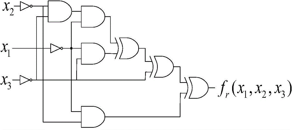
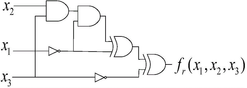
[0039] In the present embodiment, taking the example of Table 1 as an example, the function corresponding to a logic circuit with 4 inputs is used by the method of the present invention f ( x 0 , x 1 , x 2 , x 3 ) = x 0 x ‾ 2 x 3 + x ‾ 0 x ‾ 1 x 3 + x ‾ 0 x 2 x ‾ ...


PUM


Abstract

The invention discloses a polarity fast conversion method for a Reed-Muller logic circuit. Fixed polarity conversion of the RM logic is achieved through the method for deleting common parts in the logic coverage corresponding to different product terms, the steps such as product term expanding, searching and deleting in a previous RM logic polarity conversion process are omitted, multiple times of expanding, repeated product term searching and deleting operation do not need to be conducted on the product terms in the whole searching process, only one time of product term expanding needs to be conducted in the whole process, repeated examination does not need to be conducted, and therefore the conversion speed is higher in the RM logic polarity conversion process through the method, the scale of circuits which can be processed is larger, and the method has higher efficiency in the aspect of polarity searching.

Description

technical field [0001] The invention relates to a simplification method of a digital logic circuit, in particular to an input variable polarity conversion method used in the simplification process of a Reed-Muller logic circuit. Background technique [0002] Digital logic circuits can be expressed in the form of "AND / OR", or in the form of "XOR / AND". The logic expressed in the form of "XOR / AND" is also called Reed-Muller logic, or RM logic for short. Compared with the "AND / OR" representation, the RM logic in the form of "XOR / AND" has a simpler circuit structure in terms of arithmetic, parity check, and circuit testability. In terms of testable design, RM logic is widely used. [0003] The structural complexity of the RM logic circuit is closely related to the values ​​of the input variables of the circuit. Taking the following example as an example, the five expressions of the RM logic function are equivalent. Among them, H is the value of the input variable of the circu...

Claims


Application Information

Patent Timeline
Patent Type & Authority Applications(China)
IPC IPC(8): H03M13/13
Inventor 王伦耀夏银水储著飞
Owner NINGBO UNIV
Learn More