Video image processing method and video image processing system

A technology of video image and processing method, applied in the field of video image processing method and system, can solve problems such as ghosting, and achieve the effect of solving ghosting phenomenon and good 2D image display effect

Active Publication Date: 2015-04-22
HISENSE VISUAL TECH CO LTD
View PDF3 Cites 2 Cited by
  • Summary
  • Abstract
  • Description
  • Claims
  • Application Information

AI Technical Summary

Problems solved by technology

[0006] The purpose of the present invention is to overcome the defects in the existing shutter-type 3D display technology, and provide a new video image processing method and system, which can simultaneously obtain 2D video images without ghosting when displayin

Method used


Image

  • Video image processing method and video image processing system
  • Video image processing method and video image processing system
  • Video image processing method and video image processing system

Examples


Embodiment 1

[0029] like figure 2 Shown, a kind of video image processing method comprises the steps:

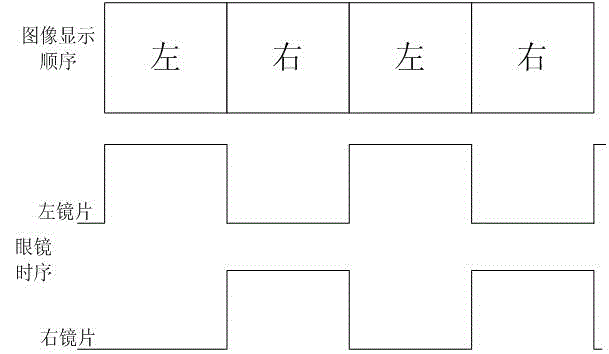
[0030] Step 101: generating left and right viewpoint images, processing the input video image into left and right viewpoint images L and right viewpoint images R arranged in left and right parts or upper and lower parts;

[0031] Step 102: Left and right viewpoint image compression processing, respectively compressing the left viewpoint image L and the right viewpoint image R into images with a resolution of 960*540;

[0032] Step 103: Calculating image compensation processing, calculating the first compensation image A and the second compensation image A' according to the left viewpoint image L and the right viewpoint image R, where it is assumed that the data of any pixel in the left viewpoint image is l, and The data of this pixel in the right viewpoint image is r, and the data of this pixel in the first compensation image is a, and the data of this pixel in the second compensation ...

Embodiment 2

[0072] like image 3 Shown, a kind of video image processing method comprises the steps:

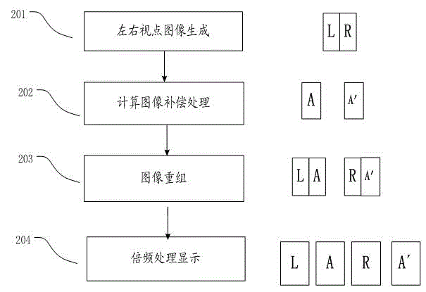
[0073] Step 201: Generate left and right viewpoint images, process the images in the input video into left and right viewpoint images L and right viewpoint images R, and process them into an image format of 1920*1080 / 60Hz for output;

[0074] Wherein, the left viewpoint image L is an image of 960*1080, and the right viewpoint image is an image of 960*1080.

[0075] Step 202: Calculating image compensation processing, calculating a first compensated image A and a second compensated image A′ according to the left viewpoint image L and the right viewpoint image R.

[0076] Further, the calculation of the first compensation image A and the second compensation image A' according to the left viewpoint image L and the right viewpoint image R specifically includes:

[0077] Wherein, the data of any pixel in the left viewpoint image L is l, and the data of the pixel in the right viewpoint image...

Embodiment 3

[0093] like Figure 4 Shown, a kind of video image processing method comprises the steps:

[0094] Step 301: Generate left and right viewpoint images, process the images in the input video into left viewpoint image L and right viewpoint image R at the upper and lower parts, and process them into an image format of 1920*1080 / 60Hz for output;

[0095] Wherein, the left viewpoint image L is an image of 1920*540, and the right viewpoint image is an image of 1920*540.

[0096] Step 302: Calculate image compensation processing, inserting the first compensation image A and the second compensation image A' into the left viewpoint image L and the right viewpoint image R.

[0097] Further, the calculation image compensation process, inserting the first compensation image A and the second compensation image A' into the left viewpoint image L and the right viewpoint image R, specifically includes:

[0098] The data of any pixel in the left viewpoint image L is l, and the data of the pix...


PUM


Abstract

The invention provides a video image processing method and a video image processing device; a 3D video image comprising a left viewpoint image and a right viewpoint image is input; a first compensation image and a second compensation image are obtained according to the left viewpoint image and the right viewpoint image, and inserted into the left viewpoint image and the right viewpoint image; four-frame images of the left viewpoint image, the first compensation image, the right viewpoint image and the second compensation image are displayed after frequency multiplication line-by-line refreshing; and the four-frame images are accumulated to form the left viewpoint image or the right viewpoint image. According to the system and the method, the technical problem that the ghosting phenomenon exists in an existing shutter 3D display technology while the watching is performed by naked eyes is solved; a 2D vide image without ghosting can be obtained simultaneously when a 3D video image is displayed, and therefore, 2D and 3D are compatibly displayed simultaneously; and the purpose that 2D and 3D images can be simultaneously watched by different crowds can be achieved.

Description

technical field [0001] The invention relates to the technical field of television display, in particular to a video image processing method and system. Background technique [0002] With the development of 3D display technology, people can enjoy 3D high-definition video without leaving home, and shutter-type 3D TV has the advantage of maintaining the original resolution of the picture, bringing people high-quality 3D video enjoyment. [0003] figure 1 It is a schematic diagram of the principle of the existing shutter-type 3D display technology, such as figure 1 As shown, in the shutter-type 3D display technology, the left and right viewpoint images are displayed alternately. When the TV displays the right viewpoint image, the right lens in the 3D glasses is turned on, while the left lens is closed to receive the right viewpoint image; when the left viewpoint image is displayed , the left lens in the 3D glasses is turned on, and the right lens is turned off to receive image...

Claims


Application Information

Patent Timeline
IPC IPC(8): H04N13/00H04N13/04
Inventor 刘卫东曹建伟黄顺明杨杰
Owner HISENSE VISUAL TECH CO LTD
Why Eureka
Try Eureka