Full cone air-assisted spray nozzle assembly

A technology of spraying nozzles and components, which is applied in the direction of spraying devices, spraying devices, liquid spraying devices, etc., and can solve the problems of not being suitable for generating and spraying full-cone spray shapes, restrictions, etc.

Active Publication Date: 2015-04-22
SPRAYING SYST
View PDF4 Cites 10 Cited by
  • Summary
  • Abstract
  • Description
  • Claims
  • Application Information

AI Technical Summary

Problems solved by technology

[0005] While external mix air atomizing nozzle assemblies are known in which a stream of liquid is atomized by pressurized air at or immediately after exiting the liquid discharge orifice of the nozzle, such nozzles do not Suitabl

Method used


Image

  • Full cone air-assisted spray nozzle assembly
  • Full cone air-assisted spray nozzle assembly
  • Full cone air-assisted spray nozzle assembly

Examples


Embodiment Construction

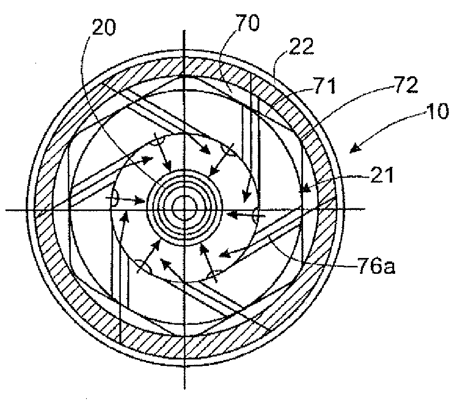
[0020] Referring now in particular to the drawings, there is shown a pressurized air assisted liquid ejection nozzle assembly 10 in accordance with one embodiment of the present invention. The spray nozzle assembly 10 in this embodiment is mounted on a conventional spray gun or head 11 having a central liquid passage 12 connected to a pressurized liquid supply 14 and circumferentially spaced (discharged) from each other for coupling to The first air channel 15 and the second air channel 16 are supplied 18 , 19 with suitable pressurized air.

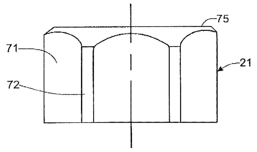
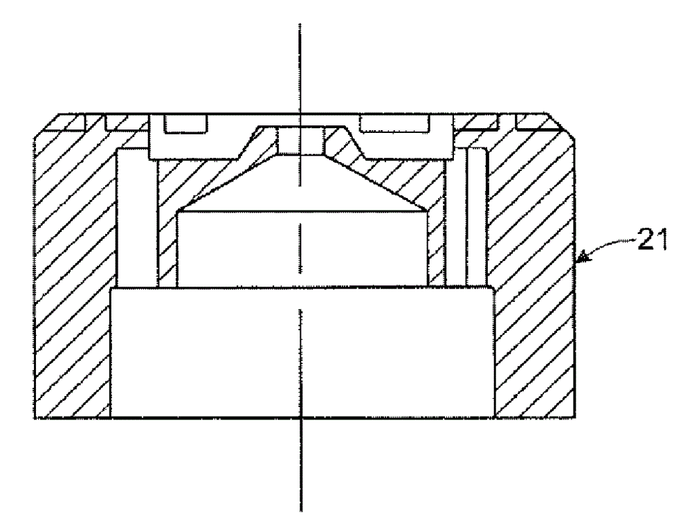
[0021] The illustrated spray nozzle assembly 10 basically includes an inner central liquid spray nozzle 20, an annular air guide or core 21 disposed about the downstream end of the liquid spray nozzle 20, and a cup-shaped nozzle body or core disposed relative to the air guide 21. Cover 22. The liquid ejection nozzle 20 has a central liquid passage 24 with a downstream inwardly converging tapered portion 25 communicating with a small diam...


PUM


Abstract

A pressurized air assisted liquid spray nozzle assembly having a liquid spray nozzle having a downstream discharge orifice for discharging a solid stream of liquid, an air guide mounted in surrounding relation to a downstream end of said liquid spray nozzle, and an outer nozzle body disposed in surrounding relation to said air guide. The air guide defines a first plurality of air passages for directing pressurized atomizing air transversely to liquid discharging from said liquid spray nozzle for atomizing the discharging liquid and a second plurality of air passages for directing shaping air tangentially to liquid discharging from said liquid spray nozzle for shaping the atomized liquid particles into a predetermined conical spray pattern.

Description

[0001] Cross References to Related Applications [0002] This application claims priority to US Patent Application No. 13 / 588,288, filed August 17, 2012, which is incorporated herein by reference. Background technique [0003] The present application relates generally to liquid spray nozzle assemblies and, more particularly, to improved spray nozzle assemblies adapted to spray a full conical spray shape. Background technique [0004] Currently, most nozzles with a spray pattern that produces a conical shape of liquid spray particles throughout the spray shape have a built-in mixing design in which a pressurized liquid and a gas stream mix and pre-atomize the resulting spray in a mixing chamber inside the nozzle. said liquid. The pre-atomized liquid is then discharged from the nozzle through a plurality of circumferentially spaced discharge holes, mixing with the multiple discharge particle streams to form a conical spray shape. A disadvantage of the nozzle assemblies descr...

Claims


Application Information

Patent Timeline
IPC IPC(8): B05B1/28
CPCB05B7/0815B05B7/10B05B7/066
Inventor J. 哈鲁奇
Owner SPRAYING SYST
Why Eureka
Try Eureka