Frictional resistance reduction device for ship
a technology of friction resistance reduction and vessel, which is applied in the direction of vehicle maintenance, vehicle cleaning, vessel construction, etc., can solve the problems of micro-bubble system requiring power, not acquired, and reducing the propulsive performance of the vessel
- Summary
- Abstract
- Description
- Claims
- Application Information
AI Technical Summary
Benefits of technology
Problems solved by technology
Method used
Image
Examples
first embodiment
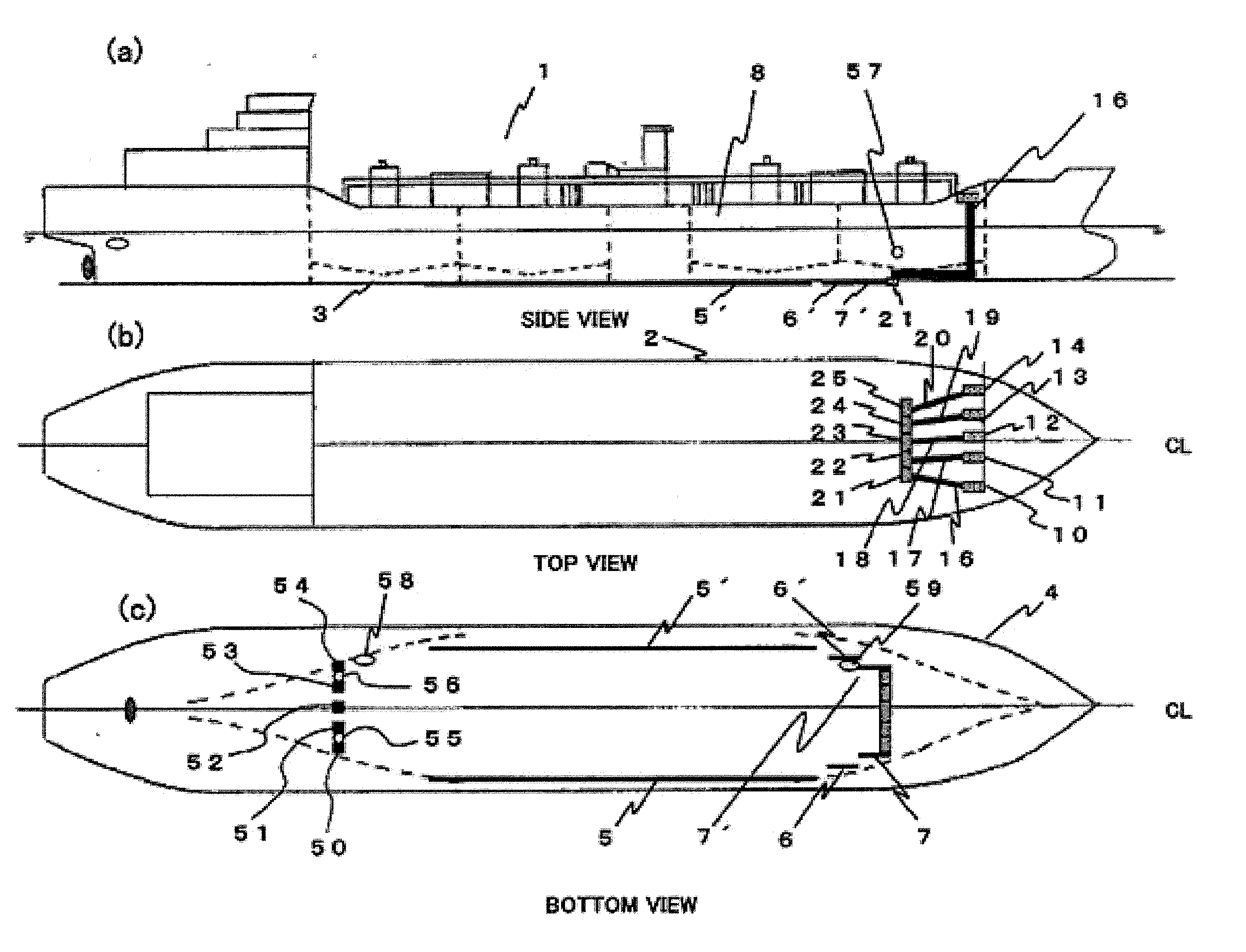
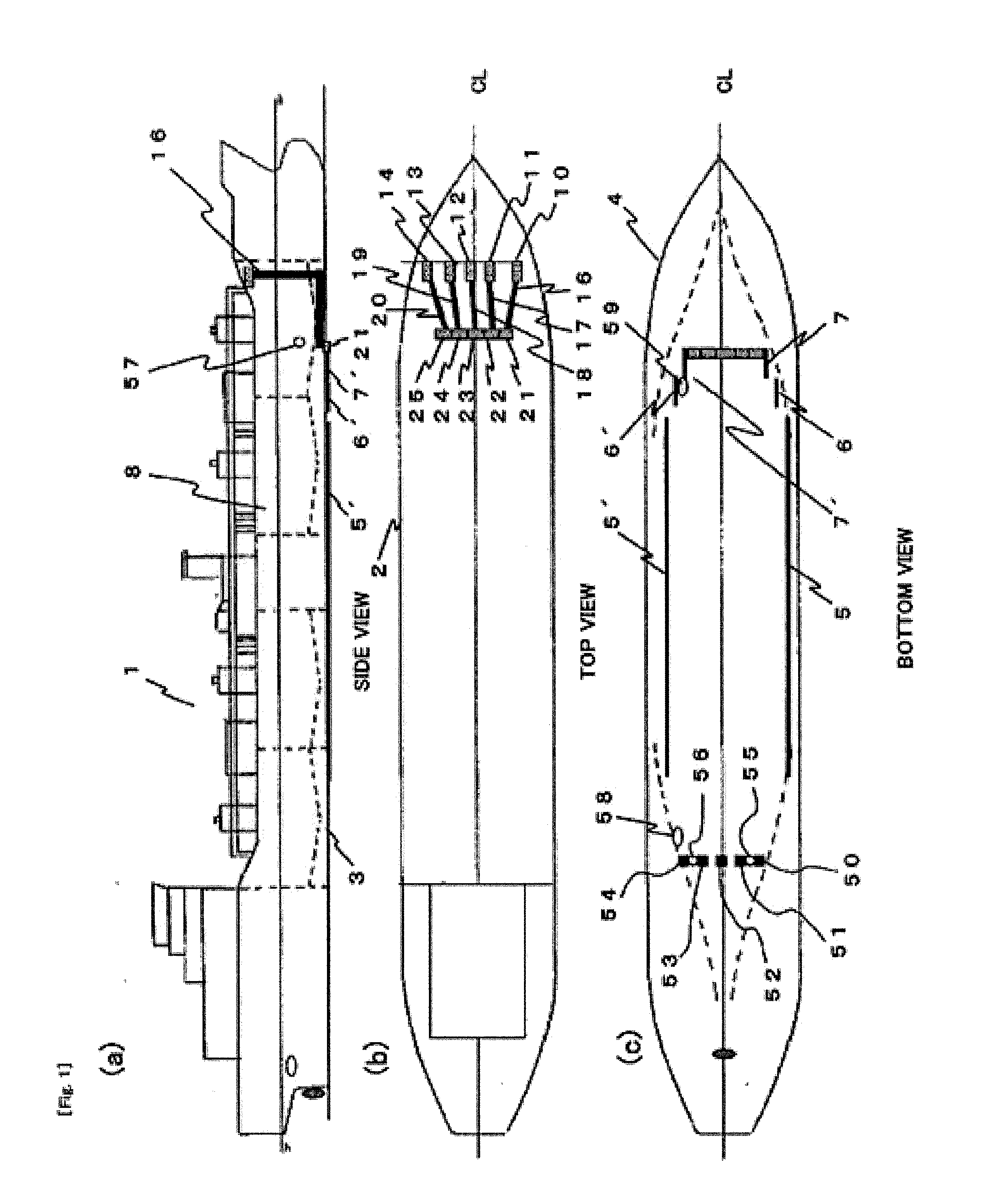
[0309]FIG. 1 (a) shows an embodiment where a frictional resistance reduction device for a vessel of an embodiment of the present invention is applied to a vessel used on ocean. FIG. 1 (a) is a side view of the vessel. FIG. 1 (b) is a top view thereof. FIG. 1 (c) is a bottom view thereof. In FIG. 1, a principal configuration is exposed for the sake of illustration.
[0310]Blowers 11, 12, 13, 14 and 15 as gas supply or charged air means are arranged in a line on a deck 2 of a vessel 1. These blowers 11, 12, 13, 14 and 15 are arranged in casing in order to avoid splash of seawater broken at the bow on the deck 2. Air, as gas, is taken from a side opposite to the traveling direction of the hull for the sake of avoiding the splash as much as possible.
[0311]The air taken into the blowers 11, 12, 13, 14 and 15 are pressurized, passes through air supply pipes 16, 17, 18, 19 and 20 having bent portions, and guided into gas outlets 21, 22, 23, 24 and 25 arranged in the proximity of the bottom 3...
second embodiment
[0344]FIG. 9 shows a second embodiment of the embodiments of the present invention. The second embodiment will be described on difference from the first embodiment. The other elements adopt configurations analogous to those in the first embodiment.
[0345]In FIG. 9, the gas outlets 21, 22, 23, 24 and 25 are arranged on the bottom 3 of the vessel 1, as shown in the figure. More specifically, a planar portion of the fore of the bottom 3 of the vessel is configured to be a so-called boat shape as indicated by broken lines. The gas outlets 21, 22, 23, 24 and 25 are arranged symmetrically with respect to the planar center line CL of the hull 4 along the fore shape of the bottom 3 of the vessel.
[0346]This allows the bubbles injected from the gas outlets 21, 22, 23, 24 and 25 to cover the entire surface of the bottom 3 of the vessel most effectively. Further, since the bubbles are along the fore shape, the bubbles can be injected from a spot such that the bubbles can be retained longest also...
third embodiment
[0366]FIG. 10 is an embodiment where a bubble retention device according to an embodiment of the present invention is applied to a vessel used in the ocean. FIG. 10 (a) shows a side view of the vessel. FIG. 10 (b) shows a top view thereof. FIG. 10 (c) shows a bottom view. A part of a principal configuration is represented in an exposed manner.
[0367]The blowers 10, 11, 12, 13 and 14 as the gas supply or charged air means are arranged in a line on the deck 2 of the vessel 1. These blowers 10, 11, 12, 13 and 14 are arranged in a casing on the deck 2 in order to avoid splash of seawater broken at the bow. For the sake of avoiding a splash as much as possible, the air as gas is taken from a direction opposite to the traveling direction of the hull.
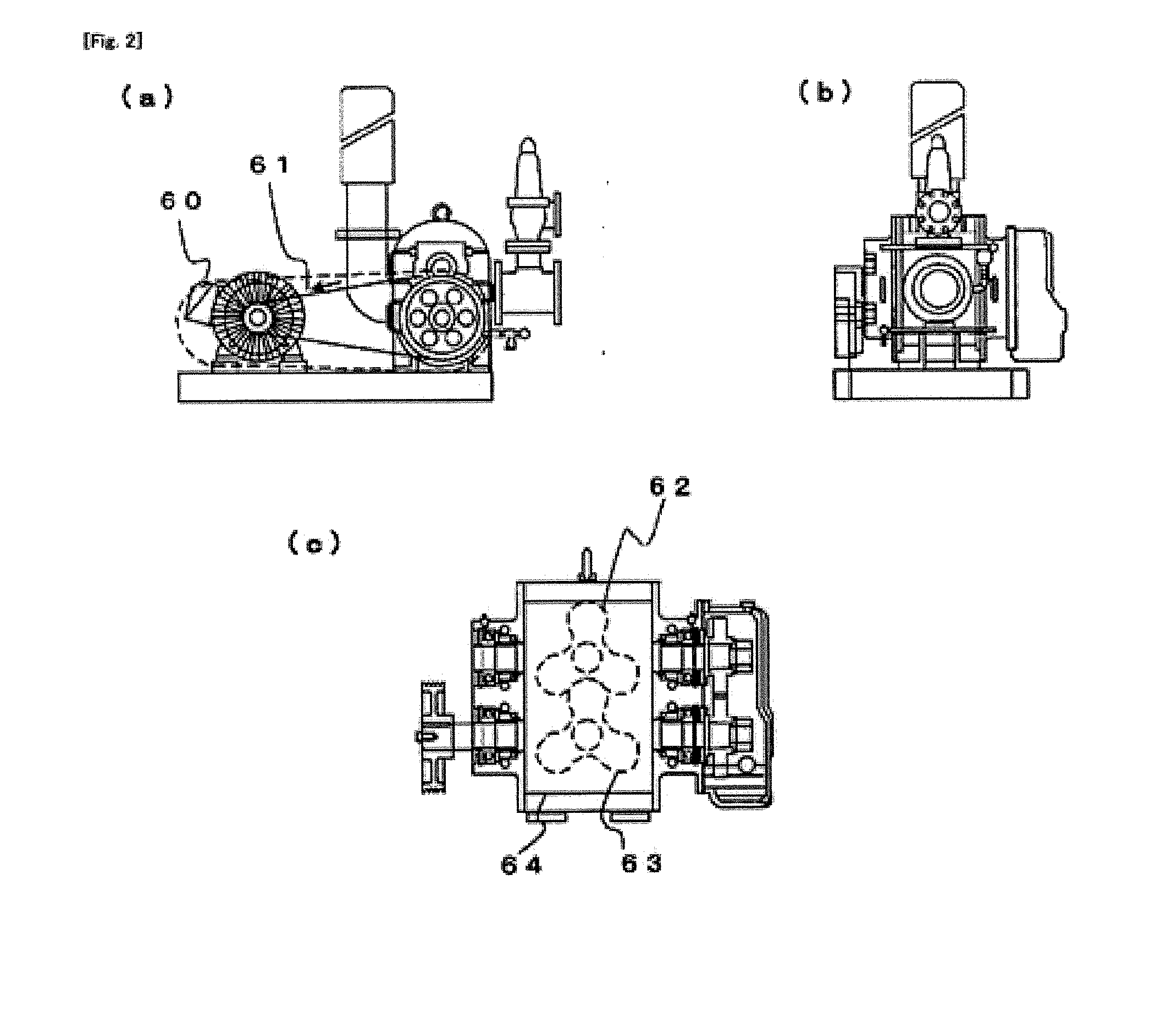
[0368]The blowers 10, 11, 12, 13 and 14 are Roots-type positive-displacement blowers, and adopt a structure (not shown) where an inverter-type motor 60 (not shown) as the drive device drives two rotors in the blower via a belt, the air taken be...
PUM
 Abstract
Description
Claims
Application Information
 - R&D
- Intellectual Property
- Life Sciences
- Materials
- Tech Scout
- Unparalleled Data Quality
- Higher Quality Content
- 60% Fewer Hallucinations
Browse by: Latest US Patents, China's latest patents, Technical Efficacy Thesaurus, Application Domain, Technology Topic, Popular Technical Reports.
© 2025 PatSnap. All rights reserved.Legal|Privacy policy|Modern Slavery Act Transparency Statement|Sitemap|About US| Contact US: help@patsnap.com


