Optical arrangement and a microscope

A technology of optical devices and microscopes, applied in the field of microscopes, can solve the problems of difficult realization of geometric shape and structural design, and achieve the effect of flexible mechanism

Active Publication Date: 2015-04-22
LEICA MICROSYSTEMS CMS GMBH
View PDF5 Cites 17 Cited by
  • Summary
  • Abstract
  • Description
  • Claims
  • Application Information

AI Technical Summary

Problems solved by technology

This device requires a specially adapted sample holding mechanism, so it is often difficult to realize in terms of geometric shape and structural design.

Method used


Image

  • Optical arrangement and a microscope
  • Optical arrangement and a microscope
  • Optical arrangement and a microscope

Examples


Embodiment Construction

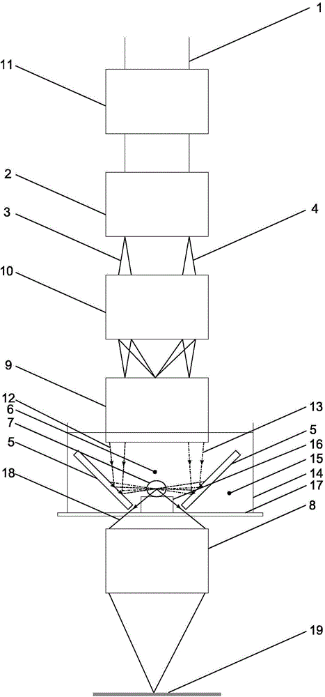
[0040] figure 1 It is a schematic diagram of the first embodiment of the optical device on the microscope of the present invention. The optical device has an illumination device for generating an illumination beam 1 extending on the illumination side. In addition, the optical device also has a beam splitting mechanism 2 and a mirror mechanism 5, the beam splitting mechanism 2 is used to divide the illumination light 1 into at least two sub-beams 3 and 4, and the mirror mechanism 5 is used to divide the two sub-beams 3 and 4 4 reflected into the illumination range 6 for planar illumination of the sample 7. In order to enable a flexible use of the structurally simple device, the optical device additionally has a detection optics 8 arranged on the side of the illumination field opposite the illumination side. In other words, all other optics for illuminating the sample 7 , such as the beam splitting means 2 and the mirror means 5 , are provided on the illuminating side in addit...


PUM


Abstract

An optical arrangement in a microscope, comprising an illumination device for generating an illumination light beam (1), running on an illumination side, a splitting device (2) for splitting the illumination light beam (1) into at least two partial beams (3, 4), and a mirror arrangement (5) for reflecting the partial beams (3, 4) into an illumination region (6) for plane illumination of a sample (7), with regard to flexible application with structurally simple means, is characterized by a detection optical unit (8) arranged on that side of the illumination region (6) which faces away from the illumination side. A microscope comprising a corresponding optical arrangement is furthermore specified.

Description

technical field [0001] The invention relates to an optical device on a microscope with an illumination device for generating an illumination beam extending on the illumination side, a beam splitter for splitting the illumination beam and a mirror device There are at least two sub-beams, and the mirror mechanism is used to reflect the sub-beams to an illumination range for planar illumination of the sample. Furthermore, the invention also relates to a microscope with corresponding optics. Background technique [0002] When observing living biological tissue with a light microscope, it is important to keep photoepitative damage to the sample as small as possible. For this purpose, a concept was developed for illuminating the detection plane of the microscope with a sheet light source. A microscopic imaging (Selective Plane Illumination Microscopy, SPIM) using selective plane illumination is realized here. In this case, the diffusion direction of the illumination light is pe...

Claims


Application Information

Patent Timeline
IPC IPC(8): G02B21/00G02B21/36
CPCG02B21/0032G02B21/367G02B21/0076G02B21/06G02B21/18
Inventor 克里斯蒂安·舒曼
Owner LEICA MICROSYSTEMS CMS GMBH
Why Eureka
Try Eureka