Clamping device for transverse deviation correction of ballastless track structure

A clamping device and technology of ballastless track, which is applied in the direction of track, track laying, track maintenance, etc., can solve the problems of inability to apply ballastless track structure for lateral clamping, inability to adapt to non-parallel stress surfaces, and difficulty in spacing adjustment, etc. Achieve the effect of improving the convenience of operation, flexible organization and good application prospects

Active Publication Date: 2019-04-16
RAILWAY ENG RES INST CHINA ACADEMY OF RAILWAY SCI +3
View PDF8 Cites 4 Cited by
  • Summary
  • Abstract
  • Description
  • Claims
  • Application Information

AI Technical Summary

Problems solved by technology

[0003] At present, a small amount of research on the clamping device has been carried out in the process of domestic ballastless track lateral correction technology research, and some simple tooling has been applied, but none of them have been able to solve the problems of insufficient clamping force, inconvenient installation, and inability to adapt to the actual field application. Problems such as non-parallel bearing surfaces, difficulty in spacing adjustment, difficulty in disassembly, etc.
The patent "A compaction limit device and method for slab ballastless track structure (CN108004855A)" and the journal paper "Research on Deviation Correction Technology of High-speed Railway CRTSⅡ Slab Ballastless Track" (Wen Xihua, "Railway Survey", 2017 No. 1 Period)" all disclose a ballastless track structure compression limit device, this type of device is used to provide lateral and vertical clamping limit of the track plate relative to the base (or supporting layer), due to the structural size, installation base Different from the binding force requirements, it cannot be applied to the lateral clamping of the entire ballastless track structure

Method used


Image

  • Clamping device for transverse deviation correction of ballastless track structure
  • Clamping device for transverse deviation correction of ballastless track structure

Examples


Embodiment Construction

[0018] The device provided by the present invention will be further specifically described below through specific embodiments with reference to the accompanying drawings.

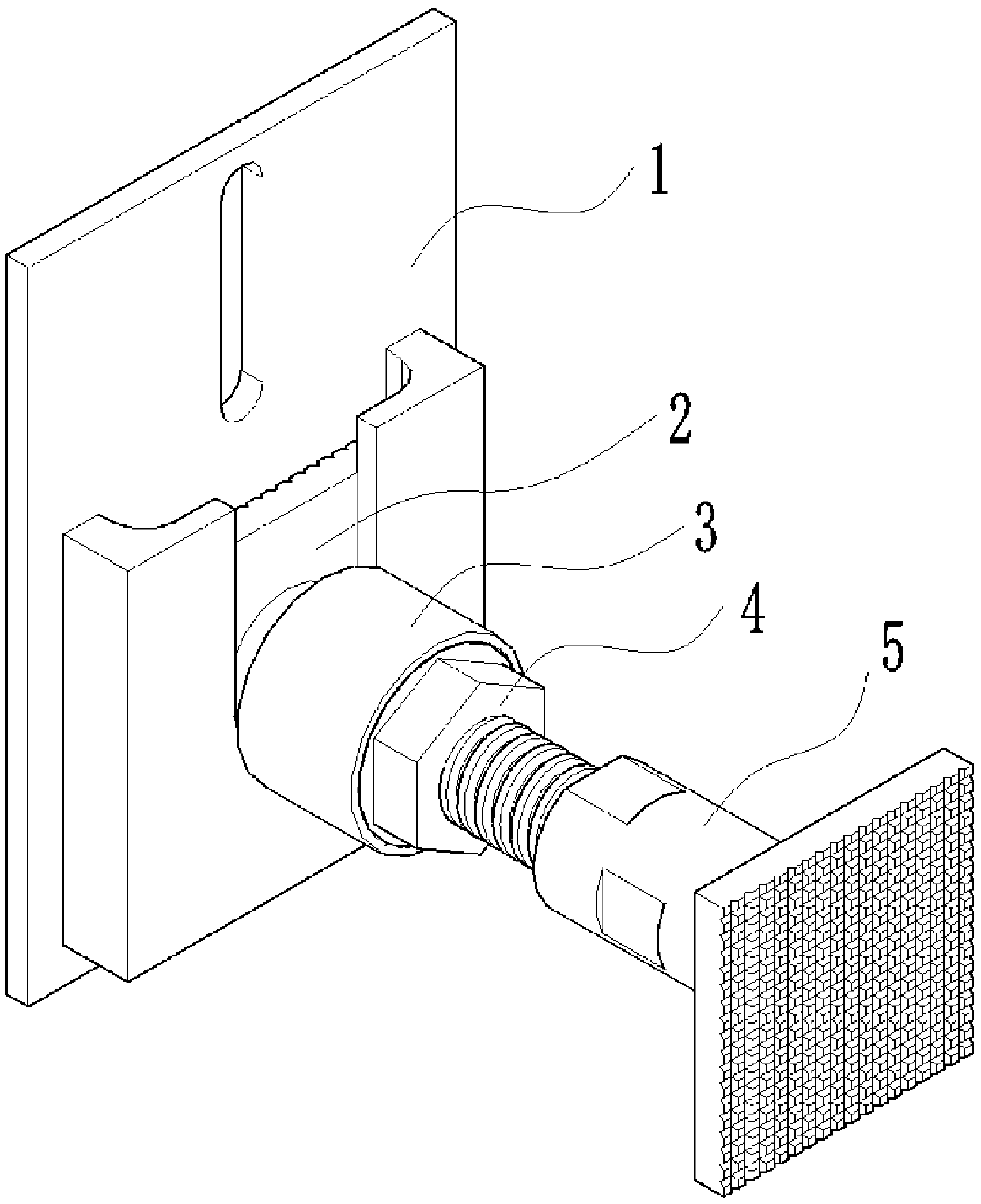
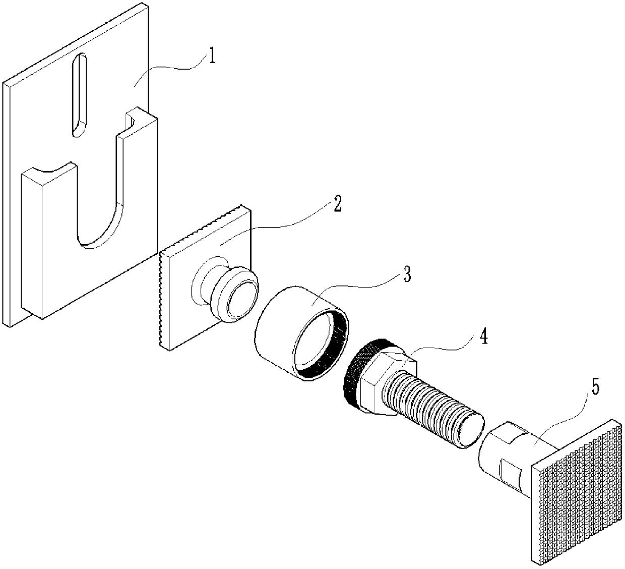
[0019] The clamping device for the lateral deviation correction of the ballastless track structure provided by the embodiment of the present invention includes an anti-falling frame 1 and a clamping push rod, wherein the clamping push rod is composed of a length adjusting sleeve 2, a length adjusting screw rod 3, and a connecting sleeve. Tube 4 and leveling end plate 5 are composed of four parts.

[0020] Before implementing the lateral correction of the ballastless track structure, the anti-falling frame 1 is installed on the side of the reaction force structure on both sides of the track structure on the side of the track structure through the oblong hole on its bottom plate by using expansion bolts.

[0021] The length-adjusting sleeve 2, the length-adjusting screw rod 3, the connecting sleeve 4 and the ...


PUM


Abstract

The invention discloses a clamping device for transverse deviation correction of a ballastless track structure, belongs to the technical field of disease treatment for ballastless track structures ofrailways, and particularly relates to the clamping device for the transverse deviation correction of the ballastless track structure. The clamping device comprises a shedding-prevention holder and a clamping mandril, and the clamping mandril is composed of four parts including a length adjustment sleeve, a length adjustment lead screw, a connecting sleeve and a leveling end plate. The length adjustment of the clamping device is achieved through a sleeve-lead screw structure, and thus the change of spacing and clamping force of a counterforce structure (a limiting structure) and the track structure is adapted to. A spherical hinge structure is adopted for adjusting the clamping angle to a certain degree and the working condition that the structural stress surfaces at the two sides of the clamping device are not parallel can be adapted to. The shedding-prevention holder is adopted for solving the problems that detaching and installing are complicated, and the clamping mandril easily falls. Through the design of combination of multiple parts, the workload of spot operation is reduced. Through the light and compact structure, the weight is reduced on the premise of guaranteeing functions, and the operation convenience is improved.

Description

technical field [0001] The invention belongs to the technical field of disease treatment of railway ballastless track structures, and in particular relates to a clamping device for lateral deviation correction of ballastless track structures. Background technique [0002] In recent years, the lateral deviation of my country's railway ballastless track structure has gradually emerged. The task of lateral deviation correction of ballastless track structure has become more and more serious, and the deviation correction technology has become more and more mature. The overall idea of ​​these rectification technologies is to first debond between the structural layers of the ballastless track or between the ballastless track and the surface layer of the subgrade bed (tunnel inverted arch backfill layer) to reduce the lateral rectification resistance, and then use mechanical pushing Lateral correction is carried out by means of the method, and finally the lateral stability of the tr...

Claims


Application Information

Patent Timeline
Patent Type & Authority Applications(China)
IPC IPC(8): E01B29/00
CPCE01B29/00
Inventor 郑新国刘竞潘永健谢永江张杰李育宏杜建群刘文黄成华杜勇贾桂良陈翌李书明曾志程冠之董全霄刘相会杨德军周骏郁培云李世达王伟唯谢清清饶云兵
Owner RAILWAY ENG RES INST CHINA ACADEMY OF RAILWAY SCI
Why Eureka
Try Eureka