
Heart rate detection mattress and method

A heart rate and mattress technology, applied in the directions of hospital beds, applications, diagnostic recording/measurement, etc., can solve problems such as difficult to determine the search range, large influence of signal fluctuation, large fluctuation range, etc., to avoid the decline of detection accuracy, and to achieve good real-time performance. , the effect of high detection accuracy

Active Publication Date: 2015-04-29
常熟东南高新技术创业服务有限公司
View PDF7 Cites 17 Cited by
  • Summary
  • Abstract
  • Description
  • Claims
  • Application Information

AI Technical Summary

Problems solved by technology

However, this method has the following problems: the heart rate is affected by various factors such as the age and gender of the subject, and there is a large fluctuation range, and the search range is not easy to determine
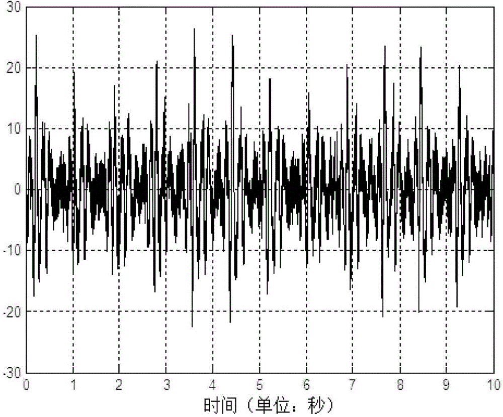
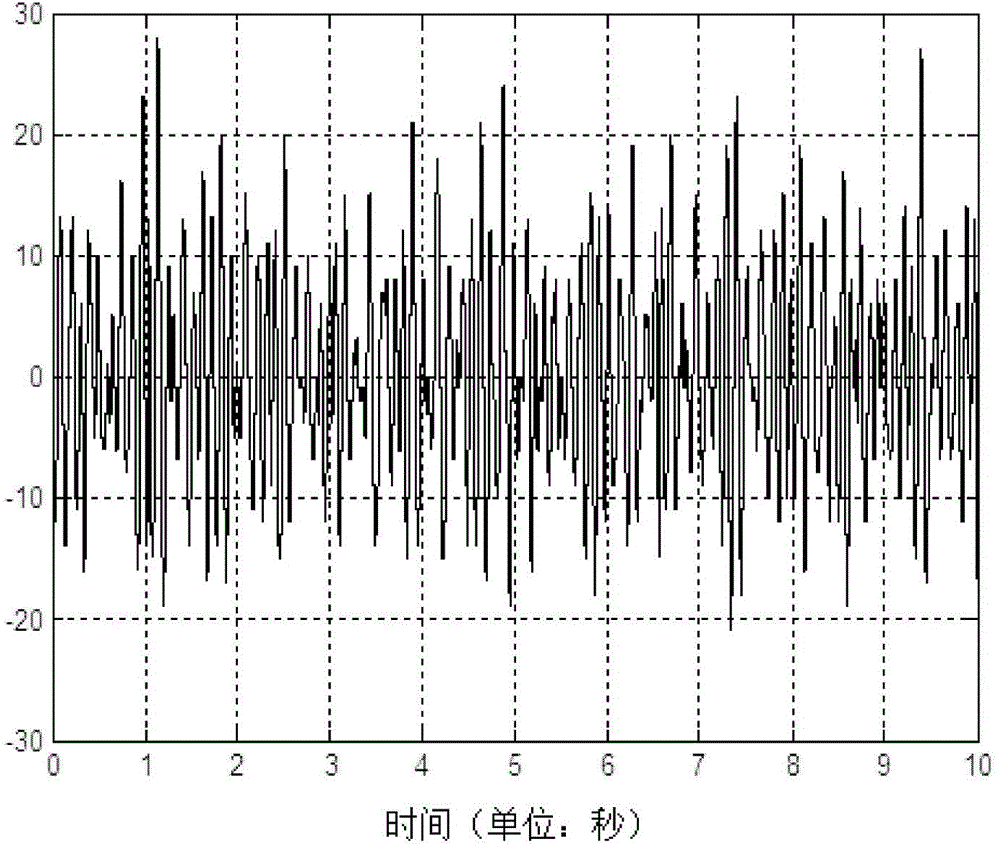
Comparing the waveforms in the figure, it can be seen that the accuracy of heart rate detection determined according to the peak period of the waveform is greatly affected by the fluctuation of the signal, especially in the case of poor signal, the obtained heart rate data is not accurate enough
[0005] In addition, the existing heart rate detection requires a special sensor on the human body, which will affect the normal sleep of the detected person, and there is also a lack of means for heart rate detection without affecting sleep in the prior art

Method used


Image

  • Heart rate detection mattress and method
  • Heart rate detection mattress and method
  • Heart rate detection mattress and method

Examples


Embodiment Construction

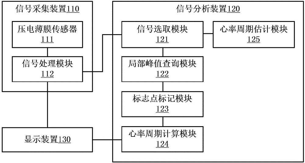
[0031] image 3 is a schematic block diagram of a mattress for heart rate detection according to an embodiment of the present invention. The mattress for heart rate detection in this embodiment may generally include: a signal acquisition device 110 , a signal analysis device 120 , and a display device 130 . The signal acquisition device 110 can convert the heart rate signal into a corresponding electrical signal, and convert it into a heart rate vibration signal that can be analyzed by the signal analysis device 120 . The signal analysis device 120 calculates and analyzes the heart rate vibration signal to obtain the heart rate cycle. The display device 130 can realize the output of the heart rate vibration signal and the calculation result of the heart rate cycle. The signal acquisition device 110 may include: a piezoelectric film sensor 111 and a signal processing module 112; the signal analysis device 120 may include: a signal selection module 121, a local peak query modu...


PUM


Abstract

The invention provides a heart rate detection mattress and method. The heart rate detection method includes the steps of obtaining a heart rate vibration signal; selecting the heart rate vibration signal through a preset time window; inquiring about the local peak values in the heart rate vibration signal in the time window, wherein each local peak value is larger than the vibration amplitudes of a preset time point before the local peak value and a preset time point after the local peak value, and every two corresponding preset time points are continuous; calculating the credibility parameters of the local peak values according to the signal amplitudes of the local peak values and the time points, and marking the local peak values with the maximum credibility parameter numerical values as identification points in the time window; calculating the time interval between every two adjacent identification points in the heart rate vibration signal to serve as the heart rate period. By means of the scheme, error caused by the individual difference of detection objects can be avoided, and the detection accuracy is high.

Description

technical field [0001] The invention relates to the technical field of medical devices, in particular to a mattress for heart rate detection and a heart rate detection method. Background technique [0002] Heart rate is the rate at which the heart beats, the number of times the heart beats per minute. Heart rate can vary with age, gender, and other physiological conditions. There are also significant individual differences in the resting heart rate of normal adults. [0003] The existing heart rate monitoring method is to use a sensor to convert the vibration signal of the heart into a corresponding electrical signal, and then determine the heart rate according to the period of the peak by searching for the peak value of the electrical signal within a certain time range. However, this method has the following problems: the heart rate is affected by various factors such as the age and gender of the subject, and there is a large fluctuation range, and the search range is not...

Claims


Application Information

Patent Timeline
Patent Type & Authority Applications(China)
IPC IPC(8): A61B5/0245A61G7/05
CPCA61B5/0245A61G7/05
Inventor 邓云庆罗川
Owner 常熟东南高新技术创业服务有限公司
Learn More