
Monitor for monitoring diaphragm motion conditions

A diaphragm muscle movement and monitor technology, applied in the field of medical devices, can solve the problems of human radiation injury, inaccurate measurement results, and inability to directly reflect the situation of respiratory muscle relaxation, so as to achieve accurate and safe monitoring and accurate and safe muscle relaxation. Effect

Inactive Publication Date: 2015-04-29
SHENZHEN MINDRAY BIO MEDICAL ELECTRONICS CO LTD
View PDF8 Cites 11 Cited by
  • Summary
  • Abstract
  • Description
  • Claims
  • Application Information

AI Technical Summary

Problems solved by technology

[0004] The anesthesiologist directly manually measures the muscle strength of voluntary muscles, such as raising the head, grip strength, opening eyes, tongue out, etc. Disadvantage: the patient needs to stay awake and cooperate
[0005] The muscle relaxation monitor monitors the mechanical effect / electrical effect / acceleration effect of muscle contraction of non-respiratory muscles (such as adductor hallucis, orbicularis oculi, etc.). Disadvantages: the purpose of applying muscle relaxants is to relax the respiratory muscles to facilitate tracheal intubation and During the operation, different muscle groups have different sensitivity to muscle relaxants and recovery speed, so the evaluation of non-respiratory muscles cannot directly reflect the muscle relaxation of respiratory muscles
[0006] In addition, muscle relaxation can also be monitored by measuring tidal volume, vital capacity, etc., which are affected by many factors, such as the depth of general anesthesia and the effect of central nervous system depressants, and the measurement results are inaccurate
[0007] In the prior art, muscle relaxation can also be detected by observing the movement of the diaphragm under X-rays. The disadvantage is that X-rays have radiation damage to the human body and cannot be monitored for a long time

Method used


Image

  • Monitor for monitoring diaphragm motion conditions
  • Monitor for monitoring diaphragm motion conditions
  • Monitor for monitoring diaphragm motion conditions

Examples


Embodiment Construction

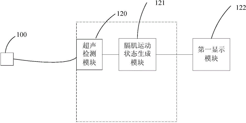
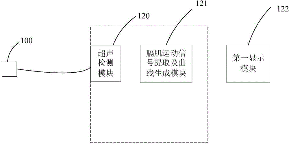
[0042] see figure 1 , the monitor that the present invention provides for monitoring the movement of diaphragm, comprising:

[0043] At least one ultrasonic probe 100 that can be fixed on the patient's body surface, and is used to transmit ultrasonic waves to the patient to scan the movement of the diaphragm;

[0044] The ultrasonic detection module 120 is connected with the ultrasonic probe 100, and is used to control the ultrasonic probe 100 to transmit ultrasonic waves to the patient and receive the echo signals obtained by the ultrasonic probe 100;

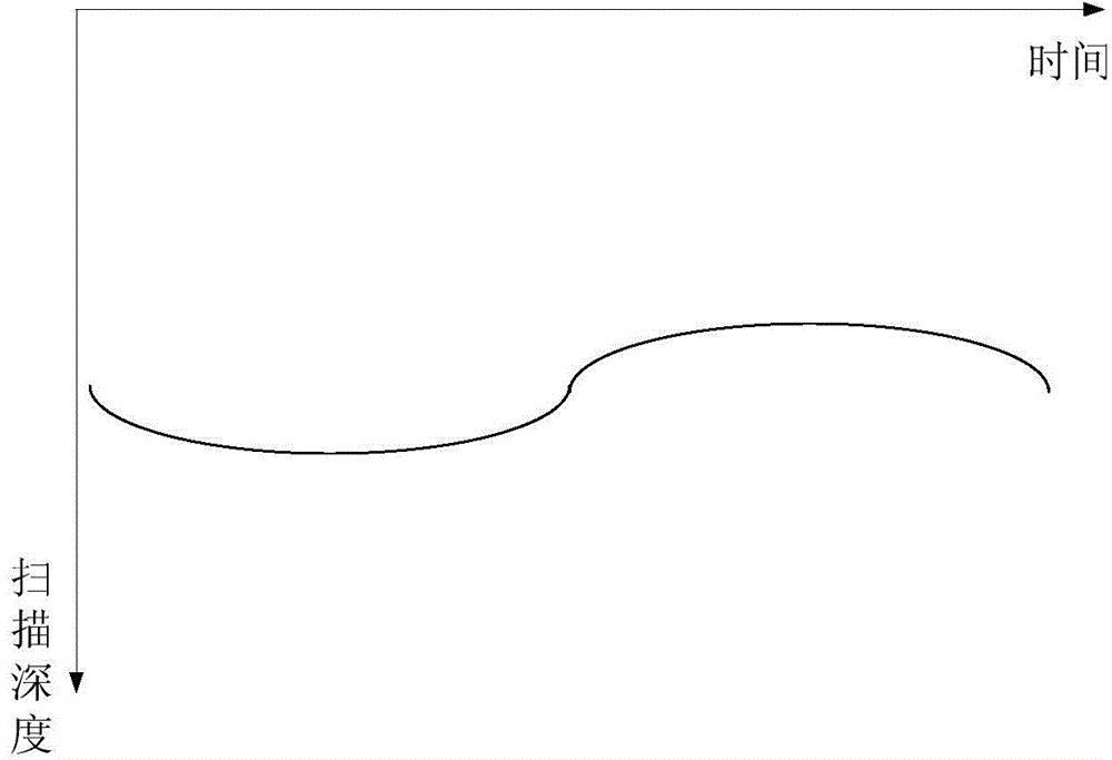
[0045] The diaphragm movement state generation module 121 is used to generate curve information or image information representing the diaphragm movement state according to the echo signal received by the ultrasonic detection module 120;

[0046] The first display module 122 is configured to display the curve information or image information generated by the diaphragm movement state generation module 121 .

[0047] In the emb...


PUM


Abstract

Disclosed is a monitor for monitoring the movement of the diaphragm, comprising: an ultrasound probe (100), which is fixed on the surface of the user's body for transmitting ultrasonic waves to the user and scanning the user's diaphragmatic movement; an ultrasonic detection module (120) connected to the ultrasound probe (100) for controlling the ultrasound probe (100) to transmit ultrasonic waves to the user, and to receive the echo signals acquired by the ultrasound probe (100); a diaphragm movement state generation module (121) for generating curve information or image information characterizing the diaphragm movement state according to the echo signals received by the ultrasonic detection module (120); and a first display module (122) for displaying the curve information or image information generated by the diaphragm movement state generation module (121). The monitor can obtain the real-time movement condition of the diaphragm and transform it into a movement image or movement curve so as to accurately and safely detect the degree of muscle relaxation.

Description

technical field [0001] The invention relates to the field of medical devices, in particular to a monitor for monitoring the movement of the diaphragm Background technique [0002] Due to factors such as the large dose range of muscle relaxants, large individual differences, and inaccurate effect failure, routine monitoring of the degree of muscle relaxation can guide the rational application of muscle relaxants during anesthesia, and can ensure the muscle relaxation requirements of different stages of anesthesia. In addition, maintaining adequate recovery of neuromuscular function after surgery is a necessary condition to ensure that patients can maintain adequate ventilation and maintain airway patency, and postoperative residual muscle relaxation is the most common cause of postoperative respiratory complications. Relaxation can reduce the incidence of postoperative residual muscle relaxation and avoid postoperative respiratory complications. [0003] In the prior art, th...

Claims


Application Information

Patent Timeline
IPC IPC(8): A61B8/00A61B19/00
CPCA61B5/0205A61B8/08A61B8/4416A61B8/0833A61B8/5223G16H50/30
Inventor 刘洋王澄李勇刘硕骆永芳陈亮宋海波刘进左云霞
Owner SHENZHEN MINDRAY BIO MEDICAL ELECTRONICS CO LTD
Learn More