Standard punching sample plate

A punching plate and template technology, applied in the direction of perforating tools, metal processing equipment, manufacturing tools, etc., can solve the problems of affecting the drilling quality, low production efficiency, time-consuming and labor-intensive, etc., so as to improve the operation effect, increase the cost rate, reduce the The effect of labor intensity

Inactive Publication Date: 2015-04-29
STATE GRID CORP OF CHINA +1
View PDF0 Cites 0 Cited by
  • Summary
  • Abstract
  • Description
  • Claims
  • Application Information

AI Technical Summary

Problems solved by technology

[0004] The present invention provides a standard punching template in order to solve the problems of time-consuming and labor-intensive, low production efficiency and affecting the drilling quality of the existing punching board.

Method used


Image

  • Standard punching sample plate

Examples


Embodiment Construction

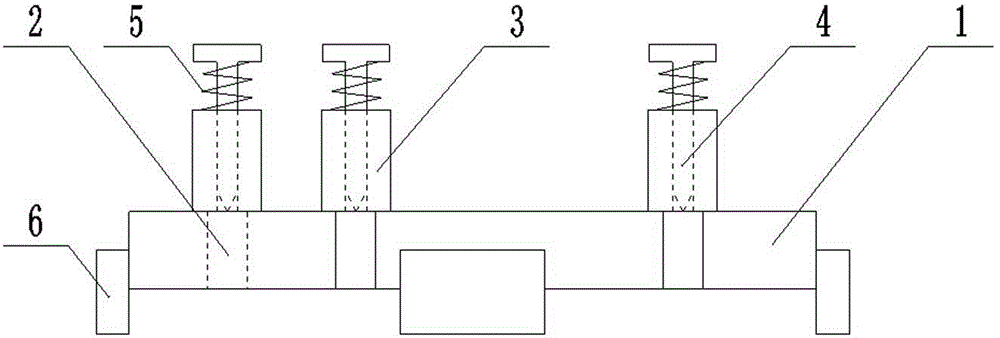
[0010] The standard punching template includes a template body 1 with the same horizontal section as the punching plate. The template body 1 is provided with through holes 2 corresponding to the drawing positions on the punching plate, and the upper surface of the template body 1 is provided with through holes 2 The guide sleeve 3 corresponding to the position, the guide sleeve 3 is pierced with a punching steel nail 4 which is closely matched with it, and between the tail end of the punching steel nail 4 and the upper end surface of the guide sleeve 3, a sleeve on the punching steel nail 4 is arranged. Return spring 5.

[0011] In the specific implementation process, several limit plates 6 are fixed on the surrounding side walls of the template body 1, so that the overlapping placement between the template body 1 and the impact plate can be realized more quickly and conveniently.


PUM


Abstract

The invention relates to a punching device applied to the electric power industry and specifically relates to a standard punching sample plate. The problems of time and labor waste, low production efficiency and influence on drilling quality of the present punching plate during a sampling process are solved. The standard punching sample plate comprises a sample plate main body, wherein the sample plate main body is identical to the horizontal cross section of the punching plate; a through hole corresponding to a sampling position on the punching plate is formed in the sample plate main body; a guide sleeve corresponding to the position of the through hole is arranged on the upper surface of the punching plate; a punching steel nail in close fit with the guide sleeve penetrates through the guide sleeve; a reset spring sleeving the punching steel nail is arranged between the tail end of the punching steel nail and the upper end face of the guide sleeve. The standard punching sample plate is reasonable and reliable in structure design, is time-saving and labor-saving during a punching process, is capable of relieving the labor intensity and increasing the operation effect, is capable of ensuring the punching precision and greatly increasing the cost rate and has the advantages of simple structure, convenience in operation and low cost.

Description

technical field [0001] The invention relates to a punching device for electric power industry, in particular to a standard punching template. Background technique [0002] The punching operation of the equipment line card is relatively cumbersome, and punching and proofing is one of the key processes. [0003] At present, when punching and proofing, the traditional method is to draw the sample after fine measurement on the punching plate, and then use steel nails to punch the holes one by one. The accuracy is not accurate enough, which affects the drilling quality. SUMMARY OF THE INVENTION [0004] The present invention provides a standard punching template in order to solve the problems of time-consuming and laborious, low production efficiency and influence on drilling quality in the existing punching plate proofing. [0005] The present invention is realized by adopting the following technical solutions: a standard punching template includes a template body with the s...

Claims


Application Information

Patent Timeline
Patent Type & Authority Applications(China)
IPC IPC(8): B21D28/34B25H7/04
CPCB21D28/34B25H7/02
Inventor 孙建新陈炜包玲
Owner STATE GRID CORP OF CHINA
Why Eureka
Try Eureka