Method and device for variable material conveying of metal coil numerical control punching

A metal coil, feeding device technology, applied in the direction of feeding device, positioning device, storage device, etc., can solve the problems of increased equipment input cost, low processing accuracy, poor stability of stamping working conditions, etc., and achieves economical practicability. , The effect of high stamping precision and process improvement

Inactive Publication Date: 2015-04-29
武汉工研光学科学技术股份有限公司 +1
View PDF6 Cites 3 Cited by
  • Summary
  • Abstract
  • Description
  • Claims
  • Application Information

AI Technical Summary

Problems solved by technology

Although this equipment layout can shorten the distance between the discharge device and the punching machine and save some floor space, the configuration of the horizontal slide rail and the drive mechanism of the discharge device itself or the high-power motor of the horizontal table will greatly increase the equipment investment cost
Moreover, the self-weight and material weight of the conventional feeding

Method used


Image

  • Method and device for variable material conveying of metal coil numerical control punching
  • Method and device for variable material conveying of metal coil numerical control punching

Examples


Embodiment Construction

[0025] The present invention will be further described in detail below in conjunction with the accompanying drawings and specific embodiments.

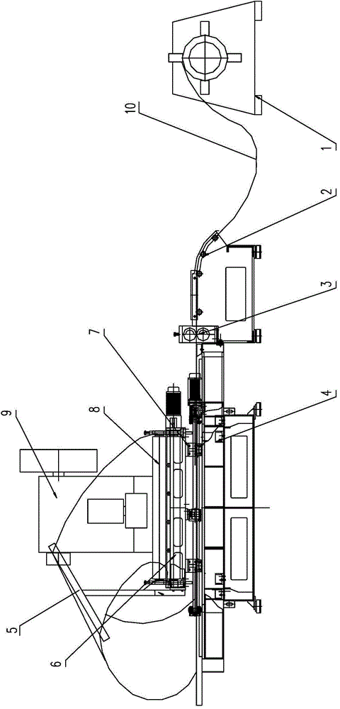
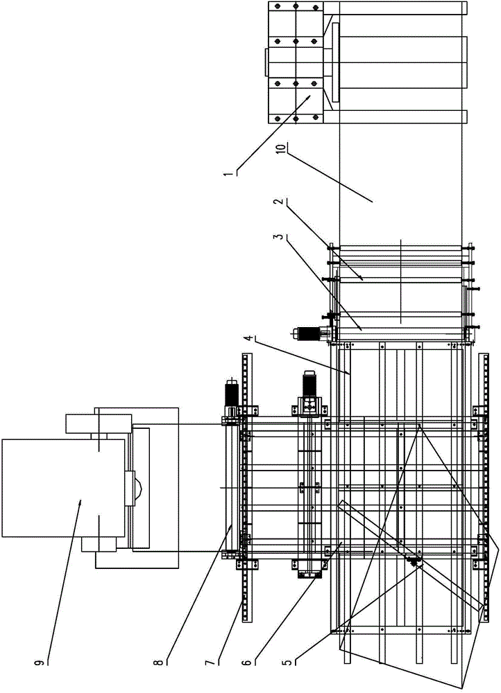
[0026] like Figure 1~2 The shown metal coil numerical control stamping feeding device is mainly composed of an uncoiler 1 used in conjunction with a punching machine 9, a horizontally fixed material receiving platform 4 and a laterally sliding material receiving platform 6 and other components. The uncoiler 1 is arranged on the front side of the punch 9, and the unwinding direction of the metal coil 10 to be processed on the uncoiler 1 is perpendicular to the longitudinal feeding direction of the punch 9 . The horizontally fixed material receiving platform 4 is arranged in front of the punch press 9 and corresponds to the position of the uncoiler 1 . A transverse conveying roller assembly 3 and a guide roller assembly 2 are arranged between the transversely fixed material bearing platform 4 and the uncoiler 1, and the transversely f...


PUM


Abstract

The invention discloses a method and a device for variable material conveying of metal coil numerical control punching. The method comprises the following steps of firstly, conveying a to-be-processed metal coil from one end of a transverse fixing material carrying table to the other end through a transverse conveying roll assembly, upwards wounding over a T-shaped turning guide rod, changing the direction by 90 degrees, conveying to a transverse slide material carrying table, and conveying to a punch press through a longitudinal conveying roll assembly to complete the longitudinal material conveying; when the to-be-processed metal coil is transversely conveyed relative to the punch press, enabling the transverse slide material carrying table to drive the to-be-processed metal coil to transversely swing. The device mainly consists of an uncoiling machine, the transverse fixing material carrying table, the transverse slide material carrying table, the transverse conveying roll assembly, the longitudinal conveying roll assembly and the T-shaped turning guide rod, wherein the uncoiling machine is vertical to the punch press, the transverse fixing material carrying table is opposite to the uncoiling machine, and the transverse slide material carrying table is arranged above the transverse fixing material carrying table. The method and the device have the characteristics that the structure is simple, the working is stable, the operation is accurate, and the two-dimensional numerical control punching of the wide metal coil without mutual interference between transverse material conveying and longitudinal material conveying is realized.

Description

technical field [0001] The invention relates to a material feeding technology in numerically controlled stamping processing, in particular to a method and a device thereof for feeding materials in numerically controlled stamping of metal coils. Background technique [0002] The CNC stamping process of metal materials is one of the processing methods widely used in machinery manufacturing. In the traditional CNC stamping process, most of the stamping raw materials are sheets. However, with the changes in the steel market in recent years, a large number of coils have entered the field of stamping processing. The traditional coil stamping processing equipment generally adopts the coaxial arrangement of the punching machine and the discharging device, and the feeding direction of the punching machine is consistent with the discharging direction of the discharging device. [0003] At present, the coils used for stamping processing are divided into two types: narrow-width and wi...

Claims


Application Information

Patent Timeline
IPC IPC(8): B21D43/02B21D43/08
CPCB21D43/026B21D43/09
Inventor 王晓晖石敏万再兴杜章晖陈晓泉卢治
Owner 武汉工研光学科学技术股份有限公司
Why Eureka
Try Eureka