Frame of axial rolling device of ring rolling machine in four pull rod structure

A technology of axial rolling and ring rolling machine, which is applied in the field of large-scale seamless ring hot-rolling forming equipment, can solve the problems of processing, manufacturing and assembling, and the frame is unsuitable due to heavy equipment and large-scale equipment. Easy to process, easy to assemble, and ensure the effect of precision

Inactive Publication Date: 2015-04-29
JINAN CASTING FORGING MACHINERY INST
View PDF7 Cites 1 Cited by
  • Summary
  • Abstract
  • Description
  • Claims
  • Application Information

AI Technical Summary

Problems solved by technology

[0006] In order to overcome the inapplicability of the frame of the axial rolling device of the existing ring rolling machine due to the heavy load and large size of the equipment, solve the problems of processing, manufacturing and assembly, as well as the problems of maintenance and disassembly

Method used


Image

  • Frame of axial rolling device of ring rolling machine in four pull rod structure
  • Frame of axial rolling device of ring rolling machine in four pull rod structure
  • Frame of axial rolling device of ring rolling machine in four pull rod structure

Examples


Embodiment 1

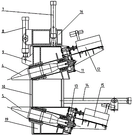
[0019] Such as figure 2 As shown, a ring rolling machine axial rolling device, its main structure consists of a balance oil cylinder 7, a main rolling oil cylinder 8, an upper slider 9, an upper tapered roller 4, a frame 10 (by an upper beam 16, a left column 17 , right side column 21, lower tapered roller seat 19 etc. are formed), following tapered roller 5, upper reduction box 11, motor (12,15), lower reduction box 13, mobile oil cylinder 14 forms.

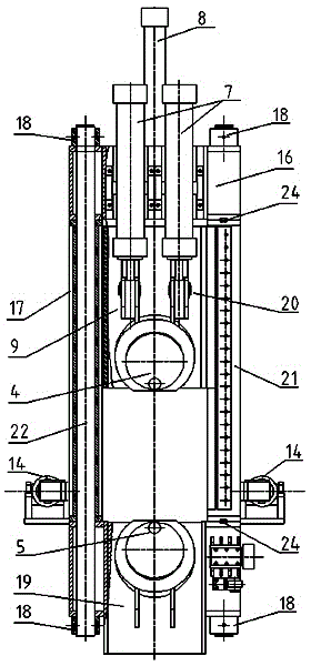
[0020] Such as image 3 and Figure 4 As shown, the first embodiment of the present invention is a frame 10 of an axial rolling device of a ring rolling machine, which includes a left side column 17 and a right side column 21 arranged on the lower tapered roller seat 19. An upper beam 16 connecting the left side column 17 and the right side column 21 is arranged above the side column 17 and the right side column 21 . Both ends of the two front tie rods 22 and the two rear tie rods 23 are provided with threads, the two front ...

Embodiment 2

[0026] Embodiment 2: The similarities between this embodiment and Embodiment 1 will not be repeated, and the difference is that Figure 7 As shown, the left side column 17 and the right side column 21 are all rectangular closed box structures, near the front and rear pull rods, vertical ribs 33) that penetrate up and down are provided, and the upper and lower ends of the left side column 17 and the right side column 21 are made of steel plates For plugging, the end is processed into a plane (referred to as a steel plate plugging plane), and an oblong keyway 32 is processed in the middle of the steel plate plugging plane for installing the flat key 24. Process the circular holes that allow the front tie rods 22 and the rear tie rods 23 to pass through on the plate block plane, and are provided with corresponding through holes that allow the front tie rods 22 and the rear tie rods 23 to pass through on the upper beam 16 and the lower tapered roller seat.


PUM


Abstract

The invention relates to a frame of an axial rolling device of a ring rolling machine in a four pull rod structure. The frame comprises a left side column and a right side column on a hypocone roller seat and an upper beam which connects the left and right side columns is arranged above the left and right side columns; threads are formed at two ends of two front pull rods and two back pull rods, the two front pull rods and two back pull rods penetrate through the hypocone roller seat, the left side column, the right side column and the upper beam and fastens the hypocone roller seat, the left side column, the right side column and the upper beam through column nuts at the upper and lower ends; flat keys are mounted on butt joint faces of the left side column and the upper beam and the hypocone roller seat respectively; flat keys are further mounted on butt joint faces of the right side column and the upper beam and the hypocone roller seat respectively; the flat keys are arranged in the middle parts of the butt joint faces along a front and back direction to play a role of positioning and bear a torsional force of a slide block rolled. The components can be respectively processed, the machining difficulty is greatly reduced, the precision is easy to ensure and the frame is convenient to assemble and maintain.

Description

technical field [0001] This application relates to a large-scale seamless ring hot-rolled forming equipment, that is, a radial-axial ring rolling machine, and in particular to a large-scale radial-axial ring rolling machine, which is used for axial rolling of a radial-axial ring rolling machine. system. Background technique [0002] The radial-axial ring rolling machine is a special equipment for hot rolling of seamless ring parts, that is, by applying radial and axial rolling forces to the heated blank, the wall thickness and height are reduced and the diameter is enlarged to manufacture seamless ring forgings . See rolling principle figure 1 . [0003] With the development of industry, wind power, aerospace, nuclear power, shipbuilding and other industries need large seamless rings with a diameter of 6000~10000mm, and the weight of a single ring can reach about 20 tons. The increase in size and heavy load of ring rolling requires the increase in size and weight of proc...

Claims


Application Information

Patent Timeline
Patent Type & Authority Applications(China)
IPC IPC(8): B21H1/06
Inventor 单宝德徐会彩叶福军周丽丽
Owner JINAN CASTING FORGING MACHINERY INST
Why Eureka
Try Eureka