Alloy hole opener

A hole opener and alloy technology, which is used in metal processing equipment, drilling/drilling equipment, manufacturing tools, etc., can solve the problems of slow hole opening speed and fast wear of blade teeth, and achieve fast hole opening speed and hardness. High strength and not easy to wear

Inactive Publication Date: 2015-04-29
滁州用朴合金工具有限公司
View PDF8 Cites 1 Cited by
  • Summary
  • Abstract
  • Description
  • Claims
  • Application Information

AI Technical Summary

Problems solved by technology

[0003] However, the tooth edge of the hole saw blade of the traditional alloy hole saw wears out quickly, and the hole opening speed is slow

Method used


Image

  • Alloy hole opener
  • Alloy hole opener

Examples


Embodiment Construction

[0016] The following will clearly and completely describe the technical solutions in the embodiments of the present invention with reference to the accompanying drawings in the embodiments of the present invention. Obviously, the described embodiments are only some, not all, embodiments of the present invention. Based on the embodiments of the present invention, all other embodiments obtained by persons of ordinary skill in the art without creative efforts fall within the protection scope of the present invention.

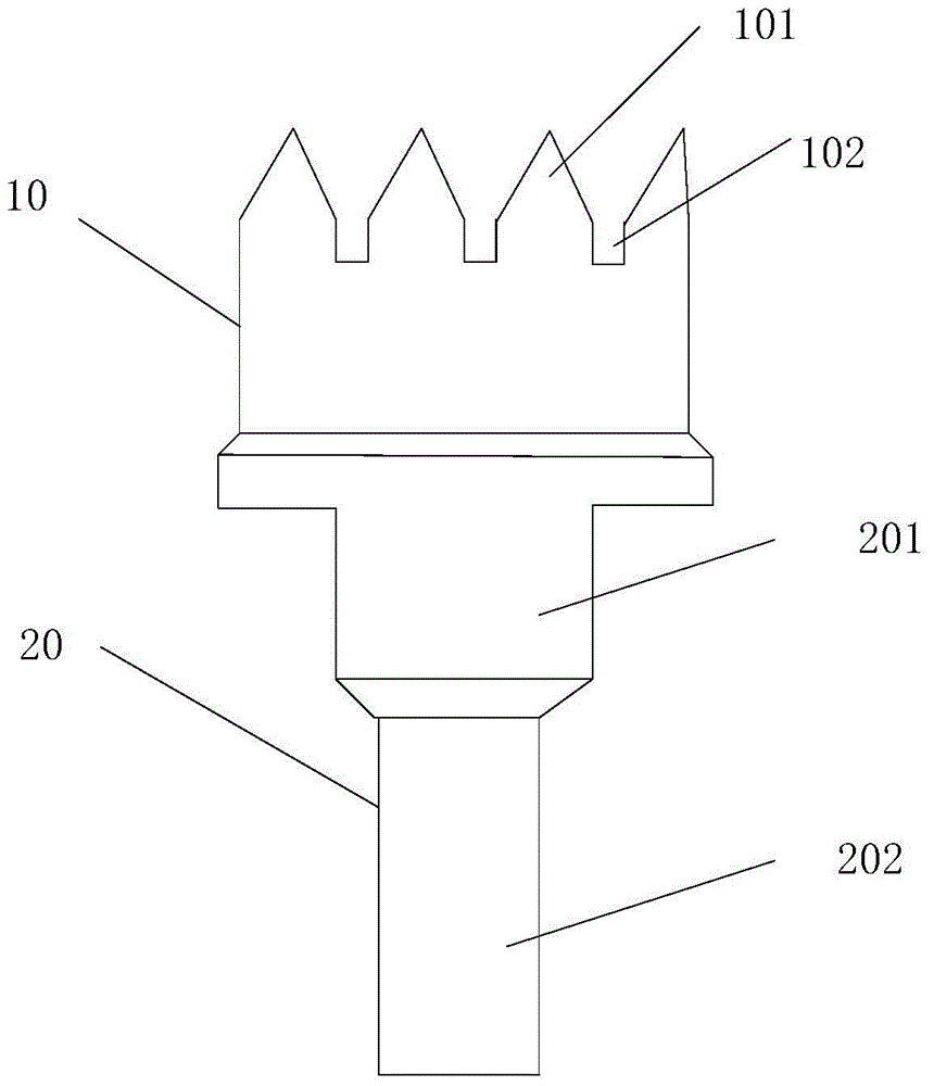
[0017] figure 1 It is a structural diagram of an alloy hole opener provided by an embodiment of the present invention, such as figure 1 As shown, a head 10 and a handle 20 connected to the head 10 are included.

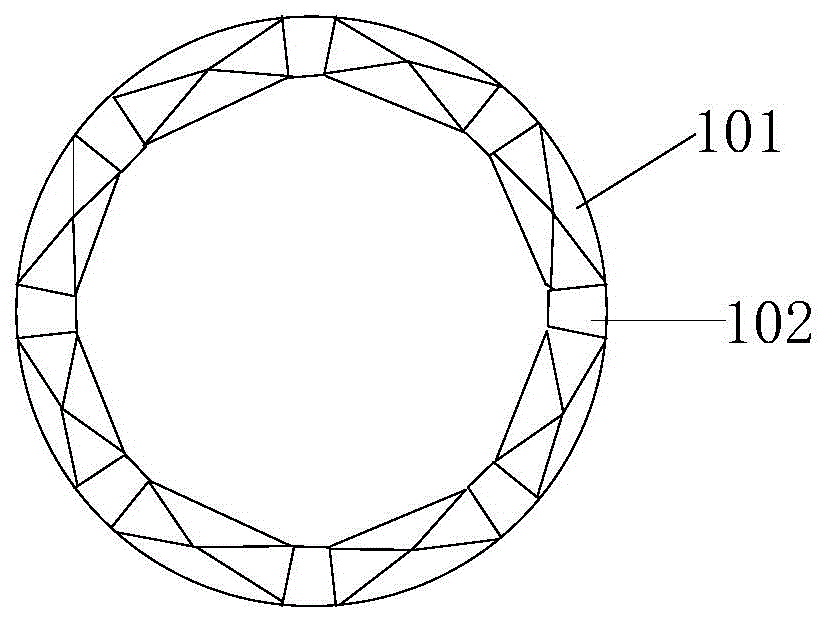
[0018] like figure 2 As shown, the head end is provided with a cemented carbide blade 101, and the cemented carbide blade 101 is in the shape of a quadrangular pyramid. Chip flutes 102 are also provided.

[0019] Among them, such as figure 1 As shown...


PUM


Abstract

The invention discloses an alloy hole opener. The alloy hole opener comprises a head part and a handle part connected with the head part, wherein hard alloy blades are arranged at the end of the head part; each hard alloy blade is in a rectangular pyramid shape; one rectangular face in each rectangular pyramid is connected with the head part; a chip discharging groove is further formed between the adjacent hard alloy blades. According to the alloy hole opener, a blade tooth opening is not easy to abrade, the service life is longer and the hole opening speed is rapid.

Description

technical field [0001] The invention relates to hardware devices, in particular to an alloy hole opener. Background technique [0002] The hole saw is also called the cutter. It is installed on an ordinary electric drill and can easily make round holes, square holes, triangular holes, and straight lines on any curved surface such as copper, iron, stainless steel, and plexiglass. , Arbitrary cutting of curves. Flexible, convenient, safe and versatile. [0003] However, the tooth edge of the hole saw blade of the traditional alloy hole saw wears out quickly, and the hole opening speed is slow. Contents of the invention [0004] The technical problem to be solved by the present invention is to provide an alloy hole opener, which is not easy to wear and tear, has a longer service time and a faster hole opening speed. [0005] In order to solve the above technical problems, the present invention provides an alloy hole opener, which includes a head and a handle connected to t...

Claims


Application Information

Patent Timeline
Patent Type & Authority Applications(China)
IPC IPC(8): B23B51/00
CPCB23B51/00
Inventor 祁长岭
Owner 滁州用朴合金工具有限公司
Why Eureka
Try Eureka