Assembly structure of disc type milling cutter

A technology of assembly structure and milling cutter, which is applied in milling cutters, milling machine equipment, manufacturing tools, etc., can solve the problems such as the inability to overlap the transition socket, the inability to maintain the tightening effect of the transition socket, and the influence of the machining accuracy.

Inactive Publication Date: 2015-04-29
常州市海伦工具有限公司
View PDF1 Cites 5 Cited by
  • Summary
  • Abstract
  • Description
  • Claims
  • Application Information

AI Technical Summary

Problems solved by technology

Since the end of the fastening screw tightens the peripheral surface of the transition sleeve, the result is: the milling cutter rotates at high speed during the working process, and is affected by the cutting resistance to generate a large torque, which directly causes the fastening screw to The fastening effect on the transition sleeve cannot be maintained. The slight consequence

Method used


Image

  • Assembly structure of disc type milling cutter
  • Assembly structure of disc type milling cutter

Examples


Embodiment Construction

[0014] The present invention will be further described below in conjunction with the accompanying drawings.

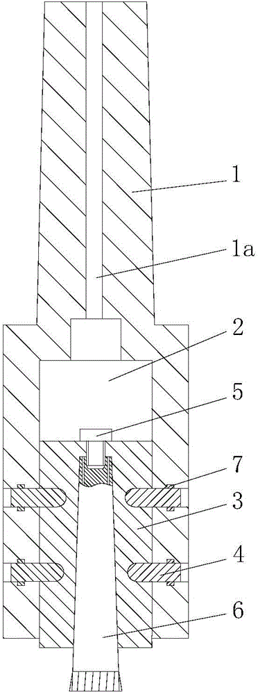
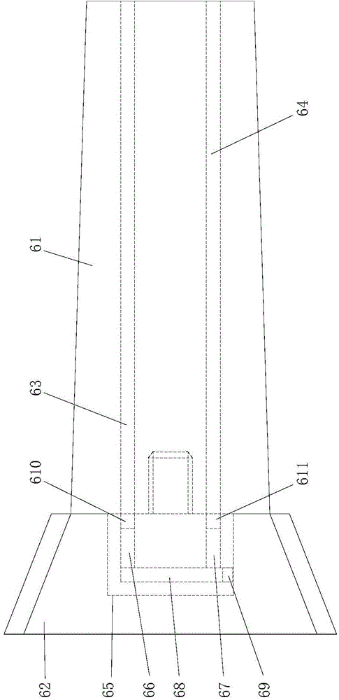
[0015] refer to figure 1 and figure 2 , The assembly structure of the disc milling cutter of the present invention includes a connecting rod 1 connected to the machine tool. The lower end of the connecting rod 1 is provided with a cavity 2 with a bottom opening, and a transition sleeve 3 is fitted in the cavity. A radial hole is provided on the circumferential surface of the connecting rod 1, and the fastening screw 4 for fastening the transition sleeve 3 in the cavity 2 of the connecting rod 1 is connected in the radial hole. The top of the transition sleeve is provided with a tension screw 5, and the inside is provided with a Morse taper hole for installing a milling cutter. One end of the milling cutter 6 is assembled in the Morse taper hole and fixed by the tension screw. The circumferential surface of the transition sleeve 3 is provided with a spherical mountin...


PUM


Abstract

The invention relates to an assembly structure of a disc type milling cutter. The assembly structure comprises a connecting rod connected with a machine tool, wherein a cavity with open bottom is formed in the lower end of the connecting rod, a transitional joint sleeve is matched in the cavity, a radial hole is formed in the circumferential surface of the connecting rod, fastening screws for fastening the transitional joint sleeve in the cavity of the connecting rod are connected in the radial hole, a tightening screw is arranged at the top of the transitional joint sleeve, a Morse taper hole for mounting the milling cutter is formed inside the tightening screw, one end of the milling cutter is assembled in the Morse taper hole and then fixed by the tightening screw, a spherical mounting hole is formed in the circumferential surface of the transitional joint sleeve, the fastening screws penetrate through the radial hole in the connecting rod and are in threaded connection with the spherical mounting hole in the transitional joint sleeve, and end parts, located in the mounting hole, of the fastening screws are spherical surfaces. The transitional joint sleeve can be fastened reliably and prevented from being thrown out and hurting people.

Description

technical field [0001] The invention relates to an assembly structure of a disc milling cutter. Background technique [0002] Small boring machines are widely used in the field of mechanical processing. The existing small boring machines usually use a T-nut tightening milling tool holder. This type of milling tool holder can meet the basic processing needs, but this type of milling tool holder has structural defects. , that is, a waist-shaped groove is opened in the middle section, so that the length of the entire boring machine milling cutter device is longer. This structure reduces the milling strength and rigidity of the milling tool handle, and it is easy to generate vibration during milling and reduce the milling speed. [0003] The publication number is CN201783689U, which discloses a boring mill milling tool holder, which mainly includes a boring tool bar. The lower end of the boring tool bar is provided with a cavity with a bottom opening. connection, the top of the...

Claims


Application Information

Patent Timeline
IPC IPC(8): B23C5/26B23C5/08
CPCB23C5/26B23C5/08B23C5/28
Inventor 曹大龙
Owner 常州市海伦工具有限公司
Why Eureka
Try Eureka