Saw band with a profiled back

A saw band and special-shaped technology, which is applied in the direction of band saws, saw blades, manufacturing tools, etc., can solve the problems of reduced service life of saw bands, high cutting force, high wear, etc., and achieve the effect of reducing cutting force and reducing wear

Active Publication Date: 2015-04-29
WIKUS SAGENFAB WILHELM H KULLMANN
View PDF8 Cites 1 Cited by
  • Summary
  • Abstract
  • Description
  • Claims
  • Application Information

AI Technical Summary

Problems solved by technology

This results in high cutting forces, high wear and a corresponding reduction in the service life of the saw band

Method used


Image

  • Saw band with a profiled back
  • Saw band with a profiled back
  • Saw band with a profiled back

Examples


Embodiment 1

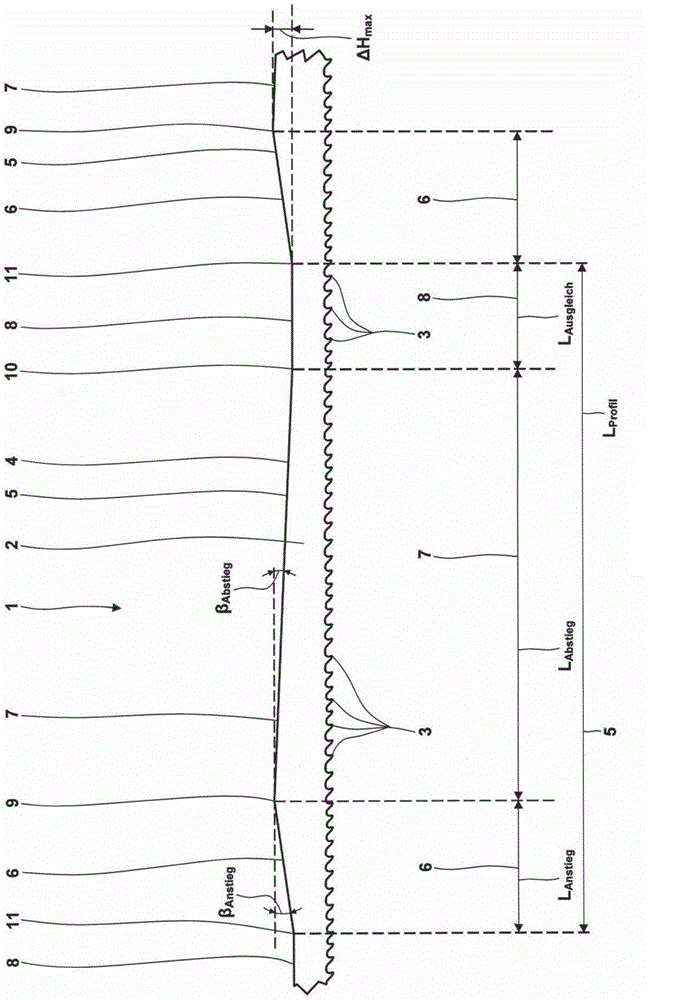
[0063] parameter unit value Inclination angle β Anstieg Spend 0.69 Inclination angle β Abstieg Spend 0.21 The length of the rising area L Anstieg mm 100 The length of the drop zone L Abstieg mm 320 The length of the compensation area L Ausgleich mm 80 Length L of back profiled section Profil mm 500 Maximum height difference △H max mm 1.2

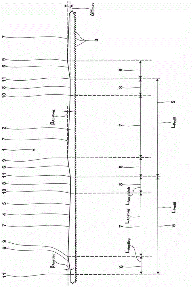
[0064] Figure 4 and Figure 5 A second exemplary embodiment of the new saw band 1 corresponding to figure 1 and figure 2 view. In this case, the belt back 4 has a symmetrically shaped belt back profile section 5 . This means that the ascending region 6 and the descending region 7 have a uniform length and a uniform inclination in terms of value.

[0065] The corresponding values ​​for this example are summarized in the table below:

Embodiment 2

[0067] parameter unit value Inclination angle β Anstieg Spend 0.33 Inclination angle β Abstieg Spend 0.33 The length of the rising area L Anstieg mm 210 The length of the drop zone L Abstieg mm 210 The length of the compensation area L Ausgleich mm 80 Length L of back profiled section Profil mm 500 Maximum height difference △H max mm 1.2

[0068] Figures 6A to 6E The novel movement of the saw band 1 in the saw machine is shown. The saw machine itself is generally constructed so that no detailed illustration or description is required. In this case, the saw band 1 has a symmetrical profiled belt-back profiled section 5 . The compensation area 8 is a recessed area.

[0069] The saw machine has guide elements 12 , which are each designed here as individual rollers 13 . The belt back 4 and thus the saw band 1 are guided by the guide element 12 in the region of the workpiece to be sawed (not shown)...

Embodiment 3

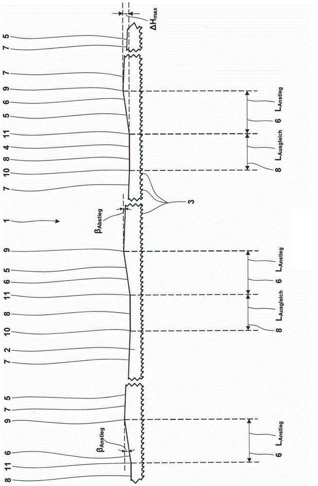
[0087] parameter unit value Inclination angle β Anstieg Spend 0.46 Inclination angle β Abstieg Spend 0.13 The length of the rising area L Anstieg mm 150 The length of the drop zone L Abstieg mm 520 The length of the compensation area L Ausgleich mm 80 Length L of back profiled section Profil mm 750 Maximum height difference △H max mm 1.2

[0088] exist Figure 8 An asymmetrically profiled saw band 1 is shown in , which is arranged here in a band saw machine (not shown in detail), which has a guide element 12 designed as a double roller 14 . In the position shown, the left double roller 14 is in contact with the beginning of the drop zone 7. The right double roller 14 is in contact with the beginning of the next rising area 6 on the right, so that overall a counterclockwise tipping position results.

[0089] Figure 9 The saw band 1 shown in has an asymmetrically shaped belt-back profiled section...


PUM

PropertyMeasurementUnit
lengthaaaaaaaaaa
diameteraaaaaaaaaa
lengthaaaaaaaaaa

Abstract

A saw band (1) includes a tooth supporting body (2), a plurality of teeth (3) being located at the tooth supporting body (2) and a back (4) being located opposite to the teeth (3). The back (4) includes a profiled back portion (5). The profiled back portion (5) includes an inclination portion (6), a declination portion (7) and a compensation portion (8). The declination portion (7) is located next to the end of the inclination portion (6) and the compensation portion (8) is located next to the end of the declination portion (7). Alternatively, the inclination portion (6) is located next to the end of the declination portion (7) and the compensation portion (8) is located next to the end of the inclination portion (6), the length of the compensation portion (8) being shorter than length of the inclination portion (6) and the length of the declination portion (7).

Description

technical field [0001] The invention relates to a saw band having a tooth carrier and a plurality of teeth arranged on the tooth carrier. Opposite the teeth, the saw band has a belt back with a belt back profile section. [0002] That is to say, the belt back does not extend in the generally linear direction of travel of the saw band, but is shaped in profile and has regions which extend at different angles relative to the generally linear direction of belt travel. . [0003] The tooth carrier and the tooth base are preferably made of metal, in particular tempered steel. The cutting edges and at least another part of the tooth tip of the tooth are likewise made of metal, special alloy tool steel or high-speed steel or of abrasive cutting material such as hard metal, cermet, ceramic cutting material or diamond. This material is harder than the material of the tooth carrier, so that the saw band as a whole is particularly suitable for cutting metallic materials. The teeth ca...

Claims


Application Information

Patent Timeline
Patent Type & Authority Applications(China)
IPC IPC(8): B23D61/12
CPCB23D61/123Y10T83/9317B23D61/12B27B33/06
Inventor J·H·库尔曼P·格莱姆C·希尔
Owner WIKUS SAGENFAB WILHELM H KULLMANN
Why Eureka
Try Eureka