Finger-shaped cutting device

A cutting equipment and finger-shaped technology, applied in the field of finger-shaped cutting equipment, can solve problems such as backwardness

Inactive Publication Date: 2015-04-29
STATE GRID CORP OF CHINA +1
View PDF4 Cites 3 Cited by
  • Summary
  • Abstract
  • Description
  • Claims
  • Application Information

AI Technical Summary

Problems solved by technology

[0015] Traditional methods and equipment for making joints are relatively backward and need to be improved urgently

Method used


Image

  • Finger-shaped cutting device
  • Finger-shaped cutting device
  • Finger-shaped cutting device

Examples


Embodiment

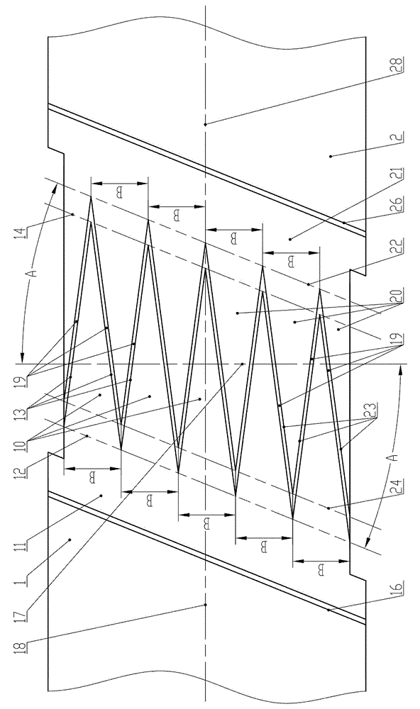
[0070] Example: see Figure 1 to Figure 13 .

[0071] A finger-shaped cutting device, characterized by:

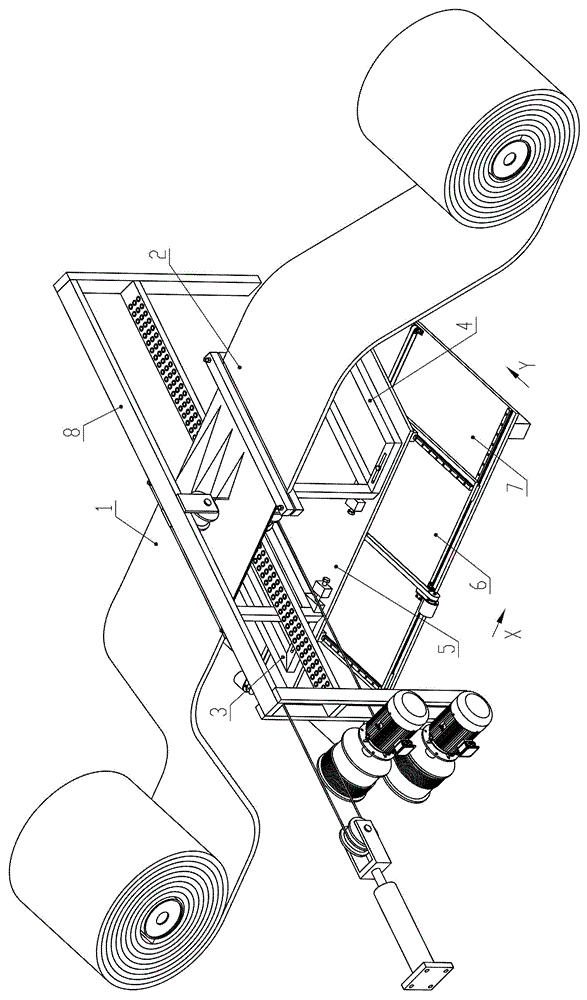
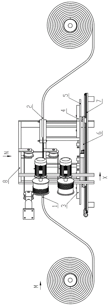
[0072] Including cutting device 8, such as Figure 10 As shown, the cutting device 8 includes a wire storage barrel 1 851, a wire storage barrel 2 861, a motor 1 852, a motor 2 862, a diamond cutting wire 83, a guide wheel and a supporting platform 84;

[0073] Such as Figure 11 As shown, there is a wire hole 842 on the belt support platform 84, and the folded belt end 1 and belt end 2 2 are placed horizontally and moved along the belt support platform 84;

[0074] One end of the diamond cutting wire 83 is fixed on the wire storage barrel one 851, and is wound many turns on the wire storage barrel one 851 to achieve the purpose of storing the diamond cutting wire 83; the guide wheels include a guide wheel one 82 and a guide wheel two 81, from The diamond cutting wire 83 of wire storage drum 1 851 walks around guide wheel 1 82, passes through wire hole 842, walks around ...


PUM


Abstract

The invention belongs to the technical field of rubber belt manufacturing equipment, and relates to a device for manufacturing a connector, in particular to a finger-shaped cutting device. The finger-shaped cutting device comprises a cutting device, a diamond cutting line and a mobile platform component, wherein the diamond cutting line performs cutting movement, a belt end 1 and a belt end 2 which are superimposed together are fixed on an upper tray component, a stepping motor drives the upper tray component to move horizontally along a finger-shaped line track, and finally the belt end 1 and the belt end 2 are simultaneously cut into finger shapes. The finger-shaped cutting device manufactures the finger shapes accurate in size, saves labor time, enables sizing material to achieve good continuity in a vulcanizing process, does not generate a fault in the middle of the sizing material, enables tensile strength of the belt connector to reach prospective strength, and is difficult to break during the use process, safe and reliable to use, high in production efficiency, and low in labor intensity.

Description

technical field [0001] The invention belongs to the technical field of rubber belt manufacturing equipment, and relates to equipment for making joints, in particular to a finger-shaped cutting equipment. Background technique [0002] A conventional belt conveyor consists of a belt, which is an endless belt that is wound between individual pulleys with appropriate tension. The driving device drives the driving roller to run, and the driving roller drives the belt to run through friction, and the other rollers and idlers follow the rotation passively. The material is loaded from the tail of the machine and unloaded from the head roller. The driving device runs continuously, and the belt can The material is continuously transported from the loading end to the unloading end and unloaded, and then returns from the non-working side. [0003] The ring-shaped belt installed on the belt conveyor generally has a relatively large circumference. For the convenience of production and tr...

Claims


Application Information

Patent Timeline
Patent Type & Authority Applications(China)
IPC IPC(8): B26D1/547B26D3/02B26D7/27
Inventor 朱明德
Owner STATE GRID CORP OF CHINA
Why Eureka
Try Eureka