Z-pin reinforced composite wind turbine blade and manufacturing method thereof

A technology for reinforcing composite materials and wind turbine blades, which is applied in the field of composite material reinforcement and can solve problems such as poor connection interface performance

Active Publication Date: 2017-01-11
NANJING UNIV OF AERONAUTICS & ASTRONAUTICS
View PDF5 Cites 0 Cited by
  • Summary
  • Abstract
  • Description
  • Claims
  • Application Information

AI Technical Summary

Problems solved by technology

[0004] The purpose of the present invention is to solve the problem of poor connection interface performance between the upper and lower half-shells of wind power blades, and provide a device that uses Z-pin three-dimensional reinforcement technology to significantly improve the connection strength and fatigue resistance of the upper and lower half-shells of wind power blades. Z-pin reinforced composite material wind power blade and manufacturing method thereof

Method used


Image

  • Z-pin reinforced composite wind turbine blade and manufacturing method thereof
  • Z-pin reinforced composite wind turbine blade and manufacturing method thereof
  • Z-pin reinforced composite wind turbine blade and manufacturing method thereof

Examples


no. 1 example

[0038] The first embodiment: as Figures 2 to 4 as shown,

[0039] The manufacturing method of Z-pin reinforced composite material wind power blade comprises the following steps:

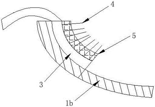
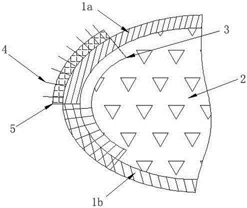
[0040] Step 1. Prepare high-performance Z-pin4 by pultrusion process, implant Z-pin4 into foam carrier 5 according to preset Z-pin4 parameters, and make foam preform containing Z-pin;

[0041] Step 2, preparing the composite material connecting layer 3 with prepreg;

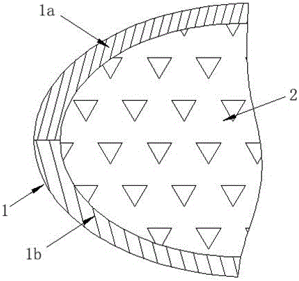
[0042] Step 3: Cover the upper half-shell 1a and the lower half-shell 1b with prepreg in the wind turbine blade mold, and place the prepreg connecting layer along the inner edge of the lower half-shell 1b, so that the prepreg connecting layer The lower half is close to the inner side of the lower half-shell 1b, and the upper half of the connecting layer 3 is located outside the lower half-shell 1b;

[0043] Step 4. Use hot pressing to bend the foam prefabricated body containing the Z-pin so that it fits the lower half of the connect...

no. 2 example

[0051] The second embodiment: as Figure 2 to Figure 4 as shown,

[0052] The manufacturing method of Z-pin reinforced composite material wind power blade comprises the following steps:

[0053]Step 1. Prepare high-performance Z-pin4 by pultrusion process, implant Z-pin4 into foam carrier 5 according to preset Z-pin4 parameters, and make foam preform containing Z-pin;

[0054] Step 2, preparing the composite material connecting layer 3 with fiber cloth;

[0055] Step 3: Cover the upper half shell 1a and the lower half shell 1b with fiber cloth in the wind power blade mold, place the fiber cloth connecting layer along the inner edge of the lower half shell 1b, so that the lower half of the fiber cloth connecting layer Close to the inner side of the lower half-shell 1b, the upper half of the connecting layer 3 is located outside the lower half-shell 1b;

[0056] Step 4. Use hot pressing to bend the foam prefabricated body containing the Z-pin so that it fits the lower half of...


PUM


Abstract

The invention relates to a Z-pin reinforced foam sandwich composite wind turbine blade and a manufacturing process thereof, belonging to the technical field of fiber composite reinforcing. The manufacturing process comprises the following steps: implanting Z-pin into a foam preform, and preparing a composite connection layer; laying an upper half shell and a lower half shell in a wind turbine blade mould, and implanting Z-pin into a connecting part of the lower half shell and the connection layer in the direction perpendicular to the shell; pouring a foaming material in a lower mould, and then closing an upper mould; after the foaming of the foaming material is finished, taking down the upper mould, implanting Z-pin perpendicular to the shell from the outside at a joint of the upper half shell and the upper half part of the connection layer, and then closing the upper mould; solidifying the Z-pin reinforced composite wind turbine blade. The manufacturing process provided by the invention has the advantages of obviously improving the connection strength and the fatigue resistance performance of the joint of the upper shell and the lower shell of the composite wind turbine blade, and avoiding the structural damage caused by ungluing of the upper and the lower shells, and the Z-pin is light in weight and high in strength, so that the requirement of the wind turbine blade for the material is met.

Description

technical field [0001] The invention relates to a Z-pin technology applied to composite material wind power blades and a manufacturing method thereof, belonging to the technical field of composite material reinforcement. Background technique [0002] Composite wind turbine blades are the key components of energy conversion in wind turbines, and they are also the most complex components. The quality of their design and manufacture is directly related to the efficiency and service life of wind turbines, and affects the performance of the entire system. Among them, foam sandwich wind turbine blades are now commonly used composite material blades because of their light weight and high strength. For large blades, due to the difficulty in overall preparation, the blades are prepared in two parts, namely the upper half-shell and the lower half-shell. There is a connection interface between the upper half shell and the lower half shell. When the blade is under force, the interface ...

Claims


Application Information

Patent Timeline
Patent Type & Authority Patents(China)
IPC IPC(8): B29C70/84B29C70/88F03D80/00
CPCB29C70/84B29C70/887Y02P70/50
Inventor 还大军李勇李吻肖军
Owner NANJING UNIV OF AERONAUTICS & ASTRONAUTICS
Why Eureka
Try Eureka