Rotor wing driving method and device

A driving method and technology of rotors, applied in the directions of rotorcraft, motor vehicles, transportation and packaging, etc., can solve problems such as complex driving process

Active Publication Date: 2015-04-29
BEIJING ZHZ TECH
View PDF5 Cites 3 Cited by
  • Summary
  • Abstract
  • Description
  • Claims
  • Application Information

AI Technical Summary

Problems solved by technology

[0004] Based on the above problems, the embodiment of the present invention discloses a rotor driving method and device to solve the

Method used


Image

  • Rotor wing driving method and device
  • Rotor wing driving method and device
  • Rotor wing driving method and device

Examples


Embodiment Construction

[0076] The following will clearly and completely describe the technical solutions in the embodiments of the present invention with reference to the accompanying drawings in the embodiments of the present invention. Obviously, the described embodiments are only some, not all, embodiments of the present invention. Based on the embodiments of the present invention, all other embodiments obtained by persons of ordinary skill in the art without creative efforts fall within the protection scope of the present invention.

[0077] In order to solve the drawbacks of the complicated driving process in the rotor driving method corresponding to the existing rotor driving system, the embodiments of the present invention provide a rotor driving method and device.

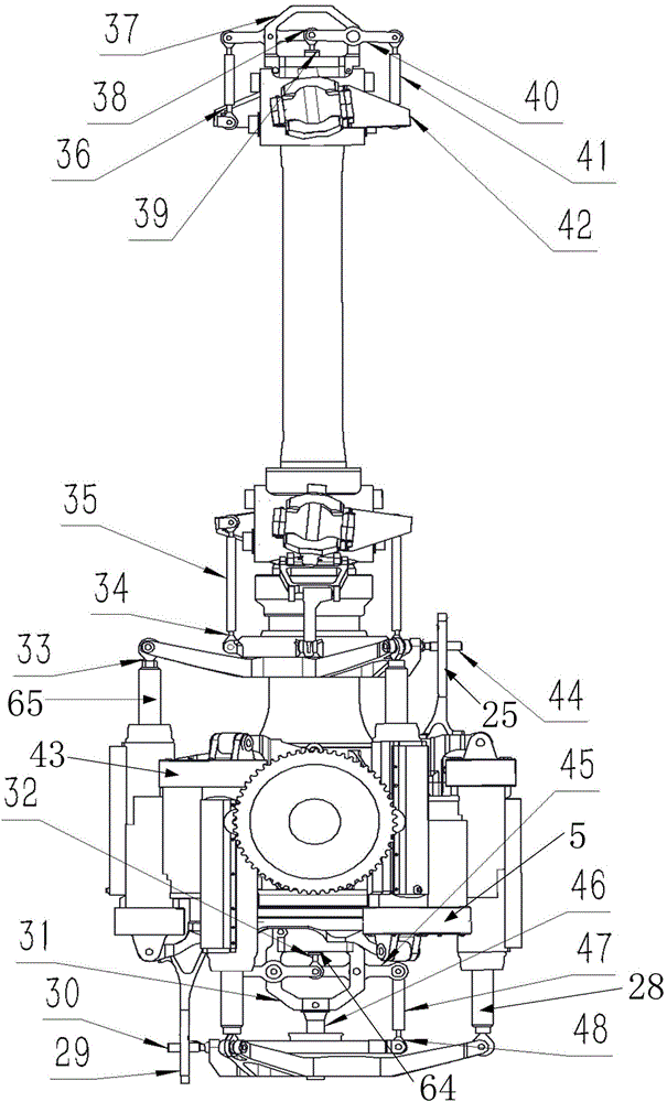
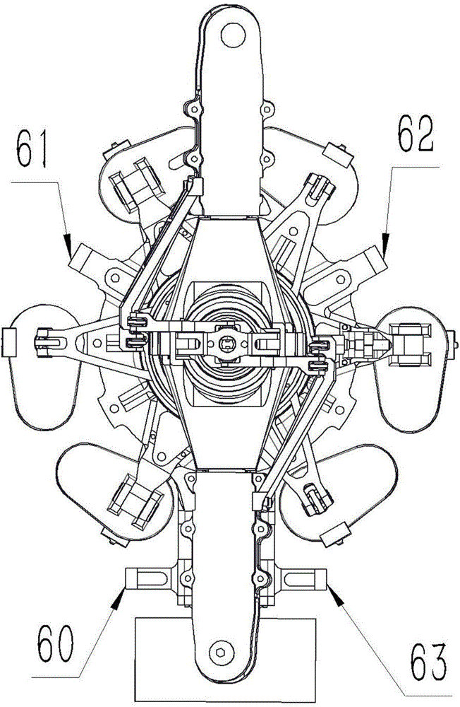
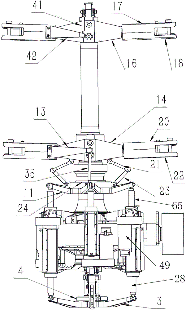
[0078] It should be noted that the rotor driving method provided by the embodiment of the present invention is applicable to a dual-rotor coaxial helicopter.

[0079] For the sake of clarity, the following first combines the atta...


PUM


Abstract

The invention discloses a rotor wing driving method and device. The method comprises the following steps: receiving a flight control command; acquiring the current rotation status of a first motor corresponding to a first steering engine, and the current rotation status of a second motor corresponding to a second steering engine; determining the first rotation status needed by the first motor according to the flight control command and the current status of the first motor; determining the second rotation status needed by the second motor according to the flight control command and the current status of the second motor; controlling the first motor to rotate at the corresponding second rotation status, thus realizing the torsion of a first paddle clamping body relative to a lower rotor hub; and controlling the second motor to rotate at the corresponding second rotation status, thus realizing the torsion of a second paddle clamping body relative to an upper rotor hub. Therefore, the defect that driving process of the existing rotor wing driving system is complicated by adopting the corresponding rotor wing driving method can be solved.

Description

technical field [0001] The invention relates to the field of twin-rotor coaxial helicopters, in particular to a rotor driving method and device. Background technique [0002] The so-called twin-rotor coaxial helicopter includes: an upper rotor and a lower rotor with the same structure, and a main shaft formed by an inner shaft and an outer shaft that rotate in opposite directions, wherein the upper rotor is installed on one end of the inner shaft, and the lower rotor is installed on the outer shaft. There is a certain distance between the upper rotor and the lower rotor; wherein, the upper rotor rotates with the inner shaft, while the lower rotor rotates with the outer shaft, so that the upper rotor and the lower rotor can rotate in opposite directions, and then the upper rotor and the lower rotor generate The torques are balanced with each other in the flight state of constant heading, no need to install the tail rotor and tail boom, and the unbalanced torque can be realize...

Claims


Application Information

Patent Timeline
IPC IPC(8): B64C27/14
Inventor 田刚印
Owner BEIJING ZHZ TECH
Why Eureka
Try Eureka