High-efficiency assembly mechanism for bottle caps

A technology for assembling mechanism and bottle cap, applied in metal processing equipment, metal processing, manufacturing tools, etc., can solve the problems of unqualified aluminum cap products, low assembly efficiency, low assembly efficiency, etc.

Active Publication Date: 2020-09-01
浙江冠利新材料股份有限公司
View PDF11 Cites 0 Cited by
  • Summary
  • Abstract
  • Description
  • Claims
  • Application Information

AI Technical Summary

Problems solved by technology

The production of existing oral liquid bottle caps is mostly assembled manually. Specifically, personnel install the rubber plugs in the aluminum caps one by one to complete the assembly process. The degree of automation is low, and the assembly efficiency is also very low, requiring a lot of manpower. Assembly work leads to high labor costs; during the assembly process, manual labor is prone to fatigue or distraction due to repetitive work, which in turn produces unqualified aluminum cover products, which makes the quality of the product unguaranteed; at the same time, aluminum The edges of the cover are usually sharp. When the personnel forcefully install the rubber plug in the aluminum cover, it is easy to scratch their hands by the aluminum cover, which is less safe.
[0003] Therefore, the existing production of oral liquid bottle caps has the problems of low automation, low assembly efficiency, no guarantee of product quality, high labor costs and poor safety.

Method used


Image

  • High-efficiency assembly mechanism for bottle caps
  • High-efficiency assembly mechanism for bottle caps
  • High-efficiency assembly mechanism for bottle caps

Examples


Embodiment Construction

[0055] The present invention will be further described below in conjunction with the accompanying drawings and embodiments, but not as a basis for limiting the present invention.

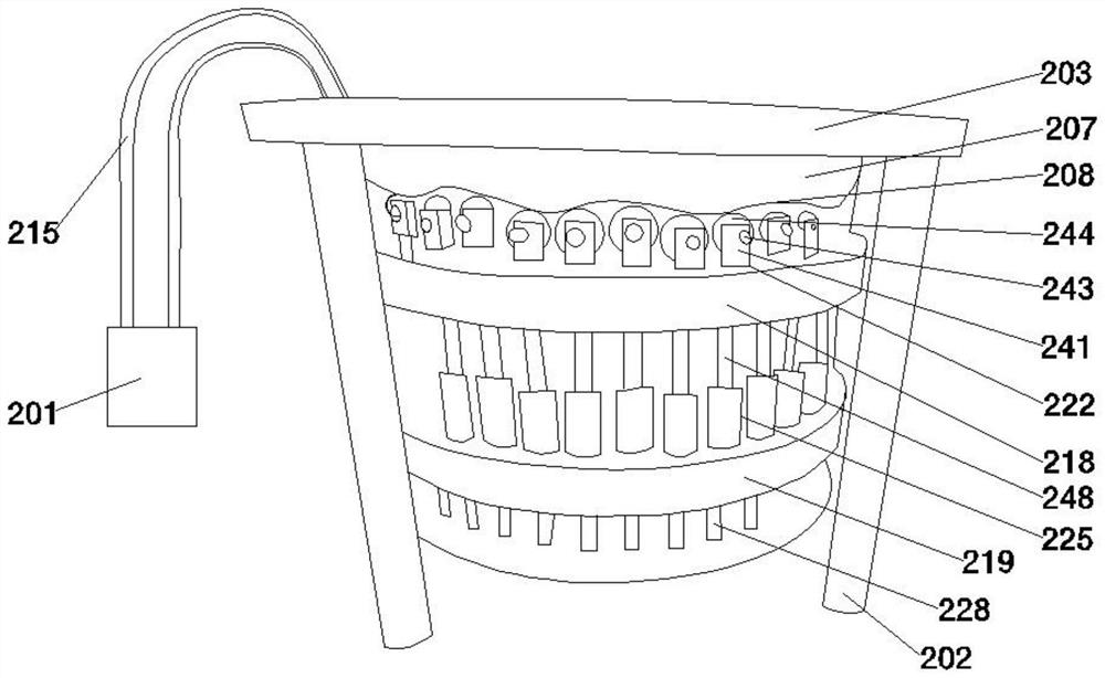
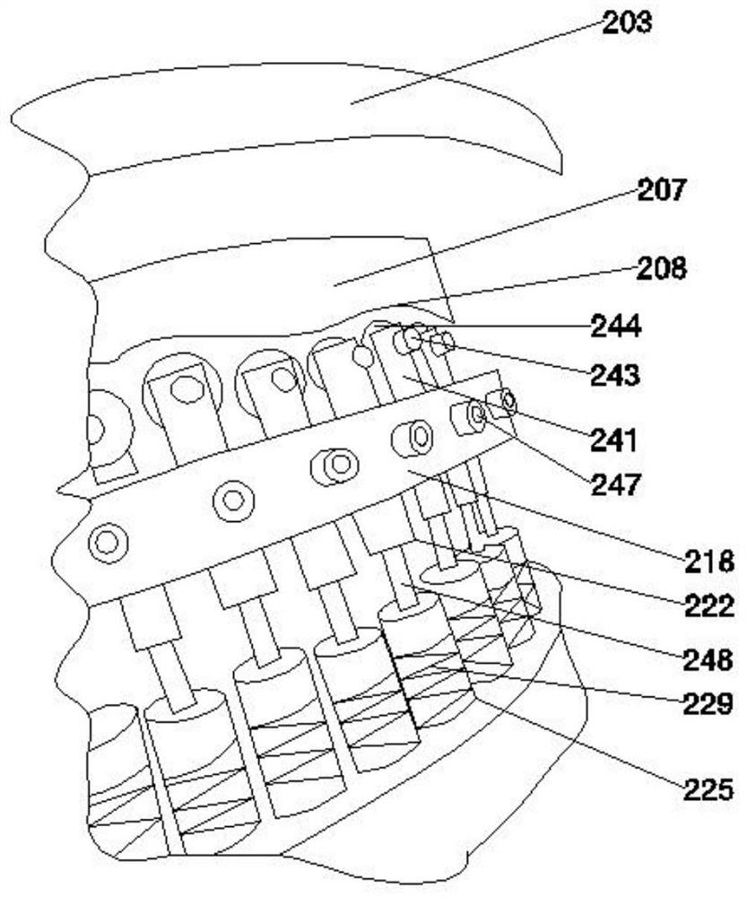
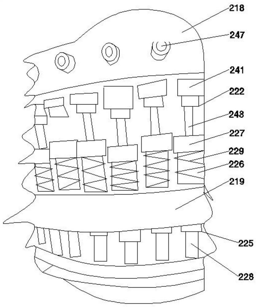
[0056] Such as figure 1 , figure 2 , image 3 , Figure 4 , Figure 5 , Figure 6 , Figure 7 , Figure 8 , Figure 9 , Figure 10 and Figure 11The shown high-efficiency bottle cap assembly mechanism includes a bracket 1, a plug mechanism 2 arranged on the bracket and a first feeding mechanism 4 in contact with the plug mechanism; the first feeding mechanism includes a first vibration assembly 401 and a set On the first conical material tray 402 on the first vibrating assembly, the first conical material tray is juxtaposed with the first spiral conveying track 403 and the second spiral conveying track 404, and the first spiral conveying track includes the first The screw conveying section 405, the second screw conveying section 406, the first twisting section 407 and the third screw conv...


PUM


Abstract

The invention relates to the technical field of pharmaceutical packaging supplies, and particularly discloses a bottle cap high-efficiency assembly mechanism comprising a bracket, an insertion and plugging mechanism and a first feeding mechanism; the first feeding mechanism comprises a first vibration component and a first tapered charging tray which is provided with a first screw conveyer track and a second screw conveyer track, and the first screw conveyer track comprises a first screw conveyer section, a second screw conveyer section, a first torsion section and a third screw conveyer section; the second screw conveyer track comprises a first screw feeding section, a second screw feeding section, a third screw feeding section and a fourth screw feeding section; and the insertion and plugging mechanism comprises a vacuum pump, a top tray, a base tray, a semicircular guide block, a regulating part, a first driving disk, a second driving disk, a conveying fluted disk, first driving parts and second driving parts. The high-efficiency assembly mechanism has the characteristics of higher automation degree and assembly efficiency, better assembly effect, product quality guarantee, lower labor cost and higher safety.

Description

technical field [0001] The invention relates to the technical field of medical packaging supplies, in particular to an efficient assembly mechanism for bottle caps. Background technique [0002] Most of the existing oral liquid bottle caps are made of aluminum caps and rubber stoppers. The way is to install the rubber stoppers in the aluminum caps and combine the aluminum caps and rubber stoppers into a whole to seal the mouth of the oral liquid bottle. The production of existing oral liquid bottle caps is mostly assembled manually. Specifically, personnel install the rubber plugs in the aluminum caps one by one to complete the assembly process. The degree of automation is low, and the assembly efficiency is also very low, requiring a lot of manpower. Assembly work leads to high labor costs; during the assembly process, manual labor is prone to fatigue or distraction due to repetitive work, which in turn produces unqualified aluminum cover products, which makes the quality o...

Claims


Application Information

Patent Timeline
Patent Type & Authority Patents(China)
IPC IPC(8): B23P19/00B23P19/02
CPCB23P19/00B23P19/001B23P19/02
Inventor 陈国伟姚卫峰
Owner 浙江冠利新材料股份有限公司
Why Eureka
Try Eureka