Electric roller

A technology of electric rollers and rollers, applied in the direction of conveyors, roller tables, conveyor objects, etc., can solve the problems of high noise, uneven operation, large volume, etc., and achieve the effect of reducing noise and convenient and accurate connection

Active Publication Date: 2015-04-29
天津诺泰克传动技术有限公司
View PDF7 Cites 2 Cited by
  • Summary
  • Abstract
  • Description
  • Claims
  • Application Information

AI Technical Summary

Problems solved by technology

[0002] In airports, stations, or production workshops, it is often necessary to use item conveying devices for cargo handling. The roller-type item conveying device is widely used due to its relatively simple structure and high transmission efficiency. However, the motor of the traditional roller-type conveying mechanism , the reducer is outside the driving drum, which has a large volume, complex structure, and inconvenient transportation. Therefore, various electric drums with built-in motors have appeared in recent years, but most of the existing electric drums have complex internal structures, high manufacturing costs, and technical requirements. High, and has the disadvantages of large drum diameter, high noise, uneven operation, inconvenient use, etc., it is difficult to popularize and apply in a large scale

Method used


Image

  • Electric roller
  • Electric roller
  • Electric roller

Examples


Embodiment 1

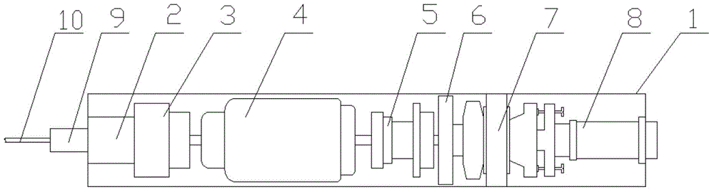
[0035] Such as figure 1 , figure 2 , image 3 An electric drum is shown, which includes a drum shell 1, a drum seat 2 is provided on one side of the drum shell 1, one side of the drum seat 2 is movably connected with the drum shell 1, and the other side of the drum seat 2 is provided with The stabilizing element 3 is movably connected with the drum seat 2, and the other side of the stabilizing element 3 is movably connected with the motor 4, and the other side of the motor 4 is provided with a gear set 5, which is connected with the motor 4 through a transmission shaft, and the gear set The other side of 5 is provided with a connector 6, which is movably connected with the gear set 5, and one side of the connector 6 is provided with a tensioning device 7, which is movably connected with the connector 6, and the drum shell 1 is provided with a roller seat 2. A cable sleeve 9 is arranged on the outside of the side, which is movably connected with the drum shell 1. The cable s...

Embodiment 2

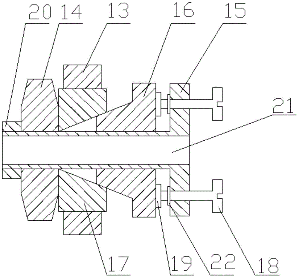
[0038] Such as figure 1 , Figure 4 , Figure 5 An electric drum is shown, which includes a drum shell 1, a drum seat 2 is provided on one side of the drum shell 1, one side of the drum seat 2 is movably connected with the drum shell 1, and the other side of the drum seat 2 is provided with The stabilizing element 3 is movably connected with the drum seat 2, and the other side of the stabilizing element 3 is movably connected with the motor 4, and the other side of the motor 4 is provided with a gear set 5, which is connected with the motor 4 through a transmission shaft, and the gear set The other side of 5 is provided with a connector 6, which is movably connected with the gear set 5, and one side of the connector 6 is provided with a tensioning device 7, which is movably connected with the connector 6, and the outside of the tensioning device 7 is provided with a rubber pad 13 , is movably connected with the tensioning device 7, and is closely attached to the drum shell 1...

Embodiment 3

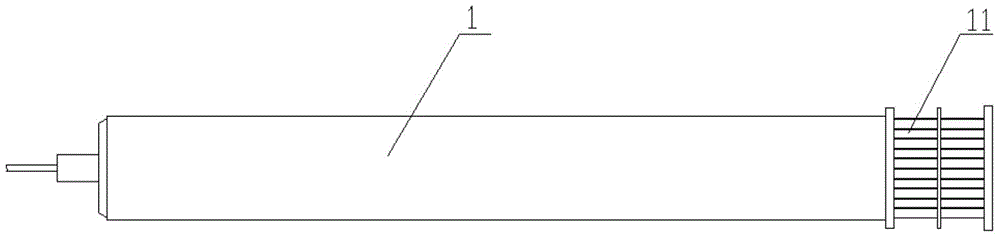
[0041] Such as Figure 6 , Figure 7 An electric drum is shown, which includes a drum shell 1, a drum seat 2 is provided on one side of the drum shell 1, one side of the drum seat 2 is movably connected with the drum shell 1, and the other side of the drum seat 2 is provided with The stabilizing element 3 is movably connected with the drum seat 2, and the other side of the stabilizing element 3 is movably connected with the motor 4, and the other side of the motor 4 is provided with a gear set 5, which is connected with the motor 4 through a transmission shaft, and the gear set The other side of 5 is provided with a connector 6, which is movably connected with the gear set 5, and one side of the connector 6 is provided with a tensioning device 7, which is movably connected with the connector 6, and the drum shell 1 is provided with a roller seat 2. A cable sleeve 9 is arranged on the outside of the side, which is movably connected with the drum shell 1. The cable sleeve 9 is ...


PUM


Abstract

The invention aims to provide an electric roller which can be rotated by utilizing an internal motor to provide power without an external motor and a reduction gearbox. The electric roller is characterized by comprising a roller housing, wherein a roller base is arranged at one side of the inner part of the roller housing; a stable element is arranged at one side of the roller base; one side of the stable element is movably connected with a motor; a gear set is arranged at one side of the motor; a connector is arranged at the other side of the gear set; a tensioning device is arranged at one side of the connector; a rubber pad is arranged on the outer part of the tensioning device, movably connected with the tensioning device, and tightly adhered to the roller housing; a transmission device is arranged on the outer part of a roller connecting device at one side of the roller housing. The electric roller has the benefits that during usage, the electric roller is seated in the whole transmission mechanism as a drive roller, and other driven rollers in the whole transmission mechanism are driven to rotate through the transmission device.

Description

technical field [0001] The invention relates to the field of mechanical manufacturing, in particular to an electric drum. Background technique [0002] In airports, stations or production workshops, it is often necessary to use item conveying devices for cargo handling. Drum type item transfer devices are widely used due to their relatively simple structure and high transmission efficiency. However, the motors of traditional drum type transfer mechanisms , the reducer is outside the driving drum, which has a large volume, complex structure, and inconvenient transportation. Therefore, various electric drums with built-in motors have appeared in recent years, but most of the existing electric drums have complex internal structures, high manufacturing costs, and technical requirements. High, and there are disadvantages such as large diameter of the drum, high noise, uneven operation, inconvenient use, etc., so it is difficult to popularize and apply it on a large scale. Conte...

Claims


Application Information

Patent Timeline
Patent Type & Authority Applications(China)
IPC IPC(8): B65G39/02B65G23/08
CPCB65G13/06
Inventor 颜子航
Owner 天津诺泰克传动技术有限公司
Why Eureka
Try Eureka