Supercharge Your Innovation With Domain-Expert AI Agents!

Standby vertical upper and lower double hooks for discharge sling chain of trolley-type thermal treatment furnace charging tray

A trolley-type, furnace-hanging chain technology, applied in the direction of load hanging components, transportation and packaging, etc.

Inactive Publication Date: 2015-04-29
杨鑫泉
View PDF5 Cites 0 Cited by
  • Summary
  • Abstract
  • Description
  • Claims
  • Application Information

AI Technical Summary

Problems solved by technology

There is no up and down double-hook type band chassis vertical hook related to the present invention similar hook reports or examples of use in life and production

Method used


Image

  • Standby vertical upper and lower double hooks for discharge sling chain of trolley-type thermal treatment furnace charging tray
  • Standby vertical upper and lower double hooks for discharge sling chain of trolley-type thermal treatment furnace charging tray

Examples


Embodiment 1

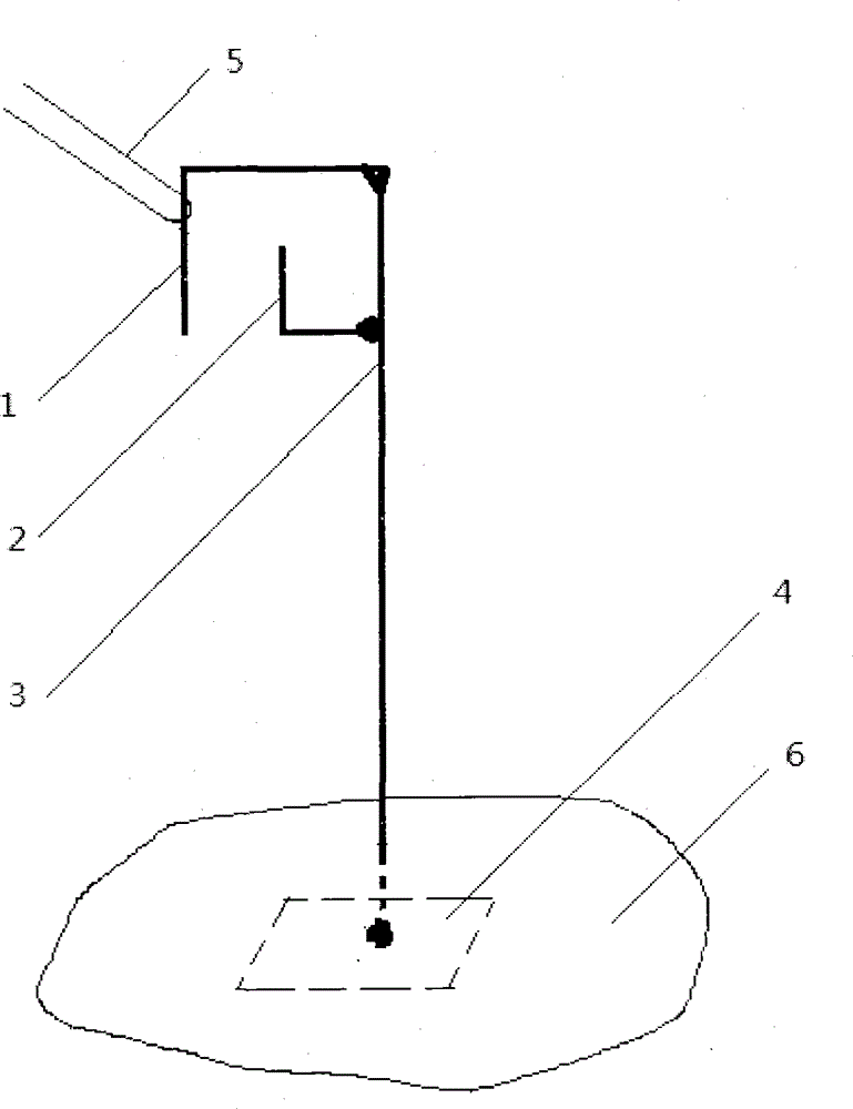
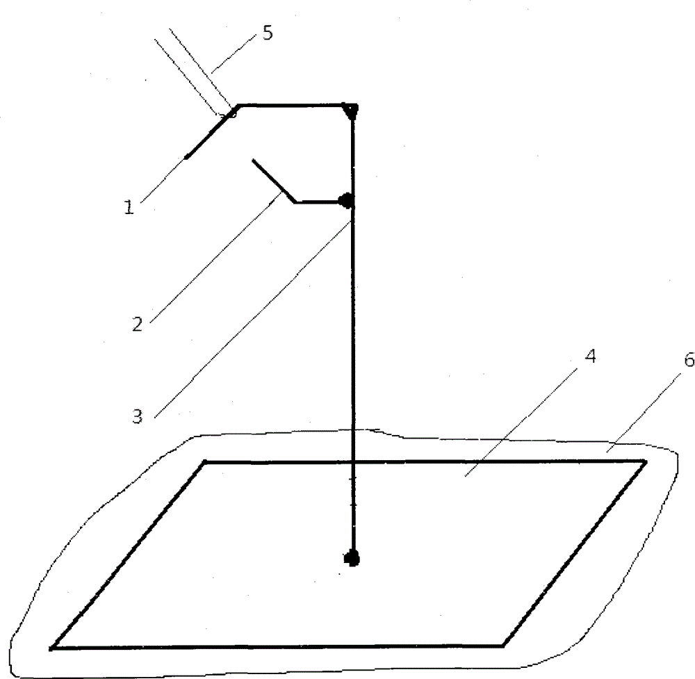
[0022] Embodiment 1: According to the above-mentioned technical solution of the present invention, a trolley-type heat treatment furnace material tray is discharged from the furnace, and the hanging chain is in place. The vertical upper and lower double hooks, its composition structure Such as figure 1 As shown: it is composed of double hook heads 1, 2, vertical rod 3, and chassis 4. The double hook heads 1, 2 are connected to the upper end of the vertical rod 3, and the vertical rod 3 is vertically connected to stand on the chassis 4; the double hook heads 1, 2 are composed of The lower finger outer hook 1 and the upper finger inner hook 2 are composed. The lower finger outer hook 1 is connected to the upper end of the vertical rod 3 with its hook point facing downward, and the upper finger inner hook 2 is connected to the upper part of the vertical rod 3 facing the side of the lower finger outer hook 1. , the hook tip faces upward, and its hook tip is located between the in...

Embodiment 2

[0023] Embodiment 2: According to the above-mentioned technical solution of the present invention, a trolley-type heat treatment furnace material tray is discharged from the furnace, and the hanging chain is waiting for the position. Vertical upper and lower double hooks, its composition structure Such as figure 1 As shown: it is composed of double hook heads 1, 2, vertical rod 3, and chassis 4. The double hook heads 1, 2 are connected to the upper end of the vertical rod 3, and the vertical rod 3 is vertically connected to stand on the chassis 4; the double hook heads 1, 2 are composed of The lower finger outer hook 1 and the upper finger inner hook 2 are composed. The lower finger outer hook 1 is connected to the upper end of the vertical rod 3 with its hook point facing downward, and the upper finger inner hook 2 is connected to the upper part of the vertical rod 3 facing the side of the lower finger outer hook 1. , the hook tip faces upward, and its hook tip is located be...

Embodiment 3

[0024] Embodiment 3: According to the above-mentioned technical solution of the present invention, a trolley-type heat-treated furnace material tray is discharged from the furnace, and the hanging chain is in place. Vertical upper and lower double hooks, the technical solutions such as its composition and structure are basically the same as Embodiment 2, the difference is: The angle between the tip of the outer hook under the finger and the horizontal plane is 30°; the angle between the tip of the inner hook on the finger and the upper part of the pole is 30° and it points upward and The above points to the direction of the outer hook. All the other are identical with embodiment two.


PUM


Abstract

The invention discloses standby vertical upper and lower double hooks for a discharge sling chain of a trolley-type thermal treatment furnace charging tray, which are used for automatically hanging a sling chain for a charging tray on the trolley surface of a thermal treatment furnace. The standby vertical upper and lower double hooks are characterized by comprising double hook heads, an upright post and a base plate, wherein the double hook heads are vertically connected to the upper end of the upright post; the vertical post is vertically connected with the upper surface of the base plate; the double hooks are composed of a downward outer hook and an upward inner hook; the downward outer hook is connected with the upper end of the upright post; the upward inner hook is connected with one side, towards the downward outer hook, of the upper part of the upright post; the tip of the upward inner hook is located between the inner side of the downward outer hook and the upper part of the upright post; the distances between the tip of the upward inner hook and the downward outer hook and between the tip of the upward inner hook and the upper part of the upright post are greater than the diameter of the sling chain; the tip of the upward inner hook is not lower than that of the downward outer hook; the double hook heads are orientated to the trolley and the charging tray of the to-be-hung sling chain on a sizing block; the terrain clearance of the downward hook head of the double hook heads, the distance between the standby vertical double hooks for the sling chain of the thermal treatment charging tray on the same side of the trolley, and the distance between the standby vertical double hooks for the sling chain of the thermal treatment charging tray on the same side of the trolley and the charging tray on the trolley can be determined by tests; and the base plate can be buried in the ground or can be put on the ground.

Description

technical field [0001] The invention relates to a ground auxiliary device for automatically hanging a driving chain on a material tray on the trolley surface of a heat treatment furnace. Background technique [0002] The furnace bottom structure of the existing industrial heat treatment general-purpose large-scale desktop furnace (resistance furnace or gas furnace) is usually a trolley, and several shim irons with the same width as the main body of the tray and a height of 250mm are placed horizontally on the trolley. The electric motor drives the machine to travel longitudinally on the track to enter and exit the furnace. Heat treatment workpieces are usually pre-installed on the tray with the same width as the top of the trolley, and then the tray is hoisted by the crane and placed on the trolley, and its longitudinal direction is parallel to the top of the trolley. The ears are located above the two sides of the trolley surface, and then the trolley is driven by the moto...

Claims


Application Information

Patent Timeline
IPC IPC(8): B66C1/22
CPCB66C1/22
Inventor 陈明彪李青山
Owner 杨鑫泉
Features
  • R&D
  • Intellectual Property
  • Life Sciences
  • Materials
  • Tech Scout
  • Unparalleled Data Quality
  • Higher Quality Content
  • 60% Fewer Hallucinations
Learn More