
Thinned fan

A technology of thin fans and fan blades, applied in the direction of non-variable pumps, pump devices, machines/engines, etc., can solve problems such as difficult to realize fan structure 1

Active Publication Date: 2015-04-29
DELTA ELECTRONICS INC
View PDF7 Cites 4 Cited by
  • Summary
  • Abstract
  • Description
  • Claims
  • Application Information

AI Technical Summary

Problems solved by technology

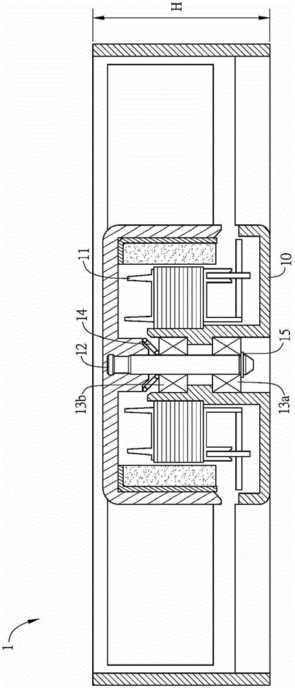
However, in the known fan structure 1, it is difficult to reduce the height H of the known fan structure 1 to less than 5 mm under the condition that the basic components cannot be reduced.

Method used


Image

  • Thinned fan
  • Thinned fan
  • Thinned fan

Examples


Embodiment Construction

[0050] A thin fan according to a preferred embodiment of the present invention will be described below with reference to related drawings, wherein the same components will be described with the same reference symbols.

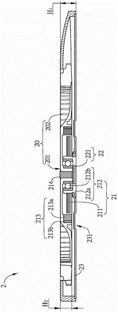
[0051] First, please refer to figure 2 , figure 2 It is a schematic cross-sectional view of the first embodiment of the thin fan of the present invention.

[0052] The thin fan 2 of the present invention includes an impeller 20 and a motor 21 . Moreover, the thin fan 2 of this embodiment may further include at least one magnetic component 22 . Wherein, at least one magnetic component 22 in this embodiment includes at least a first magnetic component 221 .

[0053] The impeller 20 has a hub 201 and a blade structure 202 . The blade structure 202 is disposed around the hub 201, wherein the hub 201 has a through hole, and the through hole can be a hollow cylinder. The fan blade structure 202 and the hub 201 illustrated in this figure can be integrated into ...


PUM

PropertyMeasurementUnit
Heightaaaaaaaaaa

Abstract

A thinned fan comprises an impeller and a motor, the impeller comprises a hub and a blade structure, and the blade structure surrounds the hub. The motor comprises a stator structure, a magnetic component, a bearing structure and a rotating shaft; the magnetic component is positioned on the inner side of the hub and annularly provided with the stator structure and comprises a magnet and a magnetism guide shell; the bearing structure comprises a bearing seat and a single ball bearing, and the single ball bearing is arranged in the bearing seat to form a storage space; the rotating shaft is clamped in the storage space. The thinned fan has the advantages that by arrangement of the single ball bearing and reduction of integral components of the thinned fan, integral height of the thinned fan is reduced to be smaller than 5mm, so that thinning is realized.

Description

technical field [0001] The invention relates to a fan structure, in particular to a thin fan. Background technique [0002] With the development trend of various electronic devices becoming thinner, in order to cooperate with the electronic devices, the structure of the fan will also be developed towards thinning. [0003] Please refer to figure 1 , is a schematic cross-sectional view of a known fan structure. The known fan structure 1 at least includes a bearing housing 10 , a stator structure 11 , a rotor structure 12 with blades, bearings 13a, 13b, a spring 14 and a retaining ring 15 . In the known fan structure 1 , two bearings 13 a and 13 b are used on both sides of the bearing housing 10 , and a retaining ring 15 is configured to fix the rotor structure 12 . The upper end of the bearing sleeve 10 is usually equipped with at least two springs 14 to provide the required preload. However, in the known fan structure 1 , it is difficult to reduce the height H of the know...

Claims


Application Information

Patent Timeline
IPC IPC(8): F04D25/08
CPCF04D25/062F04D25/08
Inventor 吕昭文王君智
Owner DELTA ELECTRONICS INC
Learn More