
Light-weight stepless gearbox

A technology of continuously variable gearbox and gearbox body, applied in the direction of gearbox, energy industry, fluid transmission device, etc., can solve the problems of poor stability, high cost, difference in wind power generation speed, etc., and achieve the effect of micro-precision adjustment

Active Publication Date: 2015-04-29
XINCHANG GENERAL MACHINERY
View PDF6 Cites 0 Cited by
  • Summary
  • Abstract
  • Description
  • Claims
  • Application Information

AI Technical Summary

Problems solved by technology

[0002] Wind power is a clean energy source with almost no pollution to the environment. Wind power is a renewable energy source and will be an important part of future energy. However, different generators for wind power generation form different power generation modes and generate different qualities of electric energy. The impact on the entire unit Indexes such as energy efficiency, electromechanical reliability, and grid capacity have a considerable impact. One of the reasons for the difference is the difference in the speed of wind power generation. Since the wind force is not constant, the size of the wind force determines the speed of the wind turbine generator. , the frequency of the electricity generated by different rotating speeds is different. The current method is to adjust the deflection angle of the leaf fan according to the different wind force to achieve the purpose of speed control, or to detect the rotating speed of the leaf fan through the leaf fan feedback mechanism. The automatic braking system controls the speed and adjusts the frequency of the electricity through the frequency converter. These measures cannot completely solve the problem. There are many shortcomings, such as high cost, low reliability, and poor stability. At present, there is an urgent need for a wind power generator that can stabilize wind power generation. Gearbox equipment for engine speed

Method used


Image

  • Light-weight stepless gearbox

Examples


Embodiment Construction

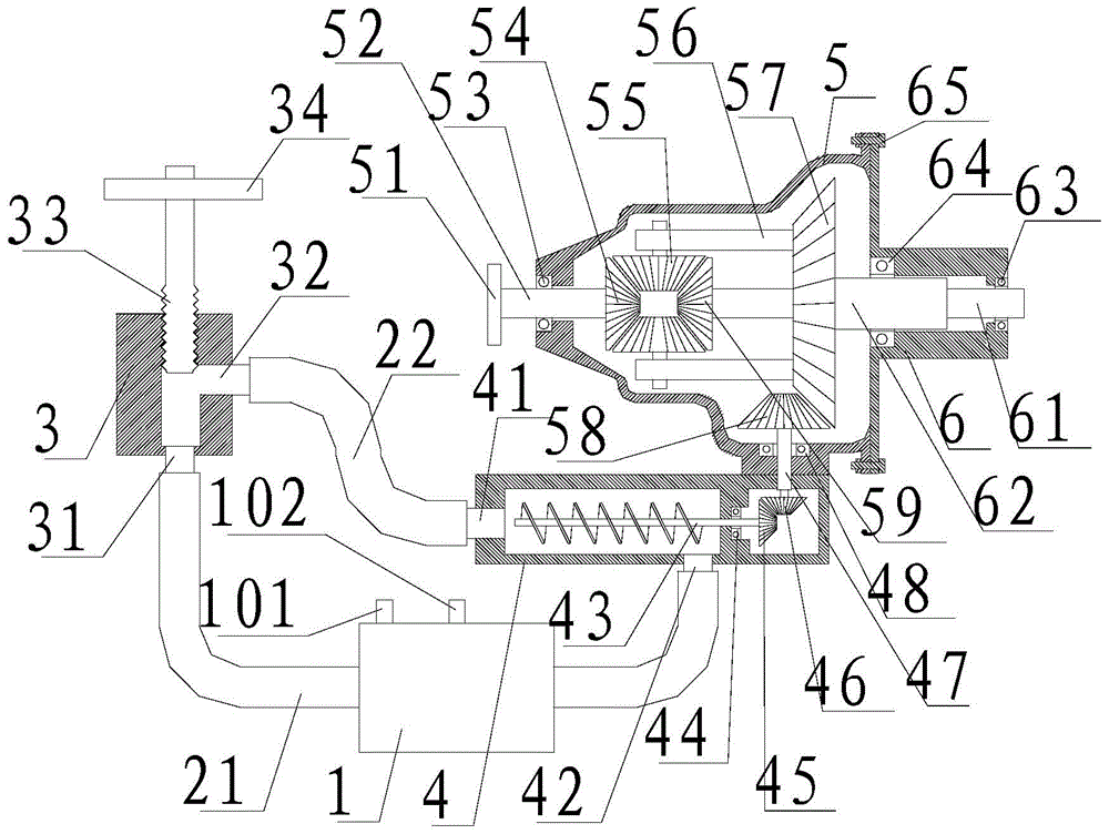
[0018] refer to figure 1 , a light-weight continuously variable transmission of the present invention, comprising a flow control valve 3, a colloidal power pump 4, a transmission case 5 and a transmission cover 6, and the transmission case 5 and the transmission cover 6 are mounted together through fixing bolts 65 , a power input shaft 61 is installed on the transmission cover 6, a speed-regulating power output shaft 62 is installed on the power input shaft 61, a power input gear 59 is installed on the power input shaft 61, and the speed-regulating power A speed regulating power output gear 57 is installed on the output shaft 62, a speed regulating gear bracket 56 is installed on the speed regulating power output gear 57, a speed regulating gear 55 is installed on the speed regulating gear bracket 56, and the gearbox body A third bearing 53 is installed on the 5, a power output shaft 52 is installed on the third bearing 53, a power output gear 54 is installed on the power outp...


PUM


Abstract

The invention discloses a light-weight stepless gearbox, which comprises a flow regulating valve, a colloid power pump, a gearbox body and a gearbox cover, wherein the gearbox body and the gearbox cover are installed in a matched way through fixing screw bolts, a power input shaft is arranged on the gearbox cover, a speed regulating power output shaft is arranged on the power input shaft, a power input gear is arranged on the power input shaft, a speed regulating power output gear is arranged on the speed regulating power output shaft, a speed regulating gear support frame is arranged on the speed regulating power output gear, a speed regulating gear is arranged on the speed regulating gear support frame, a third bearing is arranged on the gearbox body, a power output shaft is arranged on the third bearing, a power output gear is arranged on the power output shaft, and the colloid power pump is arranged on the gearbox body, and is connected with the flow regulating valve through a glue liquid return pipe and a glue liquid outlet pipe in a matched way. The light-weight stepless gearbox has the advantages that the constant speed output can be realized, the control precision is high, and the structure is simple.

Description

【Technical field】 [0001] The invention relates to the technical field of gearboxes, in particular to the technical field of a lightweight continuously variable gearbox. 【Background technique】 [0002] Wind power is a clean energy source with almost no pollution to the environment. Wind power is a renewable energy source and will be an important part of future energy. However, different generators for wind power generation form different power generation modes and generate different qualities of electric energy. The impact on the entire unit Indexes such as energy efficiency, electromechanical reliability, and grid capacity have a considerable impact. One of the reasons for the difference is the difference in the speed of wind power generation. Since the wind force is not constant, the size of the wind force determines the speed of the wind turbine generator. , the frequency of the electricity generated by different rotating speeds is different. The current method is to adjus...

Claims


Application Information

Patent Timeline
IPC IPC(8): F16H39/42F16H57/02F16H57/021F03D9/00
CPCF03D9/00F16H39/42F16H57/02F16H57/021Y02E10/72Y02P80/10
Inventor 贝永钢
Owner XINCHANG GENERAL MACHINERY
Learn More